Figure 1
My Solution:
The solution I developed involved using the VXO I designed in Figure
1.
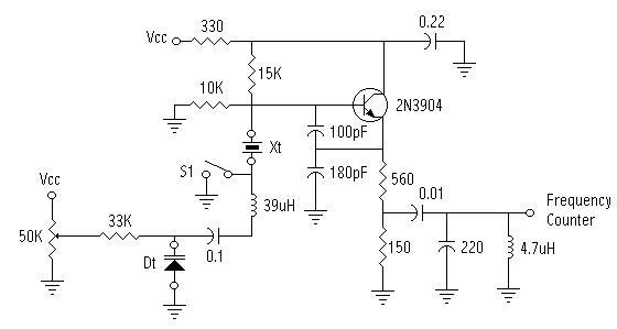
Figure 1
It is basically a Colpitts crystal oscillator, that is being "pulled" by the 39uH inductor and the capacitance at Dt. The Vcc I used for my tests was 13.8 V DC. The crystal I used at Xt was a colorburst 3.579 Mhz colorburst crystal scavenged from an old VCR. The diode and crystal both use sockets for easy substitution of components. The output of the circuit I fed into my MFJ-259 Antenna Analyzer/Frequency Counter. The switch, S1, allows me to use the same circuit to match crystals for filters, by grounding the crystal and removing the "variable" part of the crystal oscillator. I constructed the oscillator Manhattan style on a 31mm X 36mm piece of scrap PC board.
I created a baseline using known capacitor values in place of the varactor diode. Figure 2 shows the baseline data.
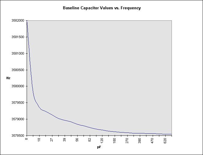
Figure 2
This gives me the ability to measure, with some degree of accuracy, varactor diodes with a capacitance of a few pF to over 200pF. Good enough to determine the capacitance of varactor diodes that I can liberate from tuners, (VCR's, TV's, Radio's, etc..).
Here are 2 curves from known varactor diodes. Both experiments show results in line with the data sheets for both diodes.
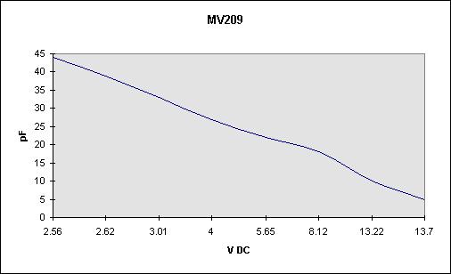
Figure 3
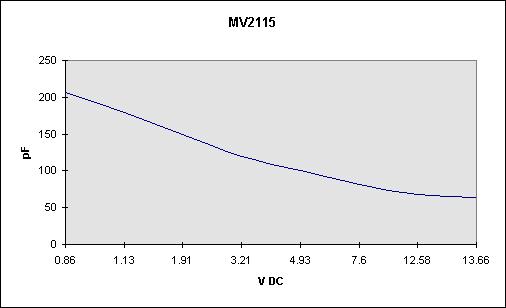
Figure 4
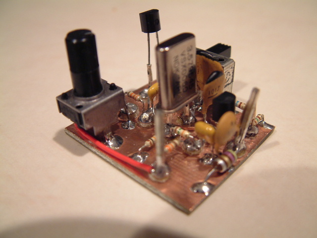
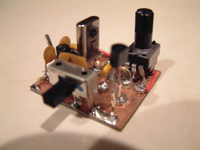
Here are a couple of pictures of the finished prototype jig.
Photo 1
Photo 2
Next, I will attempt to liberate varactor diodes from commercial electronic tuner circuits and post the results.
If you have any questions about anything you see here, please drop me
a note at [email protected].