Some antennas deployed:
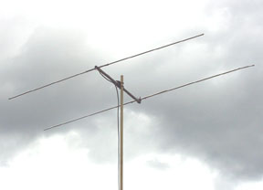
I built this antenna for portable operations on the six meter band. It has a PVC plastic boom with the driven element mounted through it. The driven element is also center insulated with a black plastic rod, as shown below. It matches well to 50 ohms direct, without a match network.

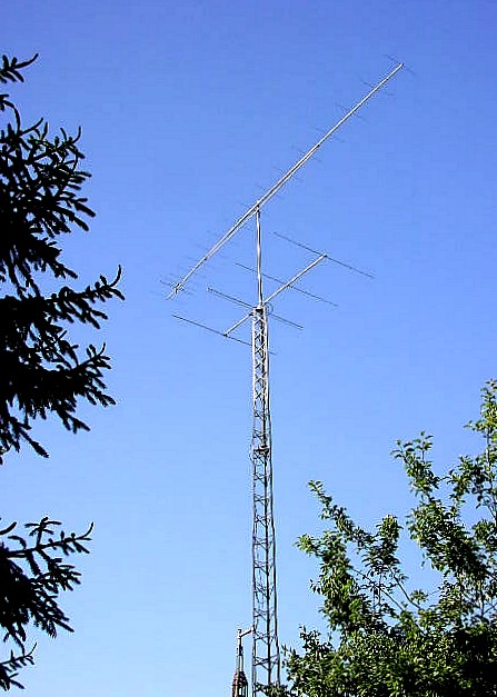
Cushcraft 17B2 yagi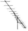
This 17 element yagi on a 31 foot boom (4.5 wavelength) and is a good standard to judge other high gain 2 meter antennas. It models and performs like similar length Yagis. It does the job dependably and with impressive gain. Very rugged and long antenna.
Homebrew 50 Mhz 4 element yagi
50 Mhz, 4 element yagi and Mt St Helens
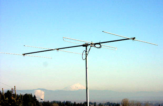
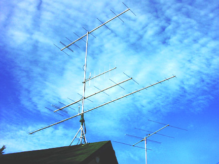
Two 8 element yagis in phase, 144 Mhz
I had excellent 144 Mhz results with a pair of vertically stacked Telrex 2M-814 yagis. These 2 wavelength, 8 element yagis have been modified by changing to folded driven elements. They are well balanced with 4:1 half wave coax baluns. I used two RG-11 75 ohm matching sections cut to odd 1/4 wavelength. AO/YO antenna modeling indicates the Telrex beams were optimized for maximum gain at 145 Mhz by design. This yagi has a narrow bandwidth with reduced F/B, typical of a maximum gain design. I had them stacked 11 feet apart for 14 dbd gain as modeled by AO in freespace. This is within 1/2 db of the 17B2 model but has a much wider azimuth pattern..
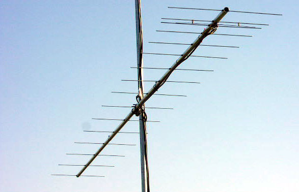
K1FO-33 432 Mhz yagi
The K1FO-33 antenna was given to me by W7SZ.
This 10.5 wavelength yagi has 33 elements and is 24 feet long. It's +/-10 degree
pattern (-3db) is razor sharp. The inertial backlash after rotating can be a problem
when trying to zero in on a signal. Sometimes the signals fade in and out
as the backlash oscillation damps out! I now have a Landwehr GasFET preamp
mounted on this antenna.
16 element 222 Mhz yagi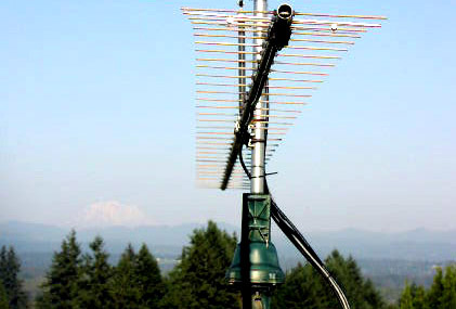
KI7JA made me a very nice yagi for 222 Mhz. It performed well during the January 2005 VHF contest, reaching Canada and Idaho with just 20 watts. This 3.9 wavelength antenna design can be found in some ARRL publications. I modeled it at almost 14 dbd gain, 20 db F/B. It uses a T-match feedpoint.
16 element 222 Mhz Yagi
K7YO antenna modeling & source files
Last update: June 3, 2017