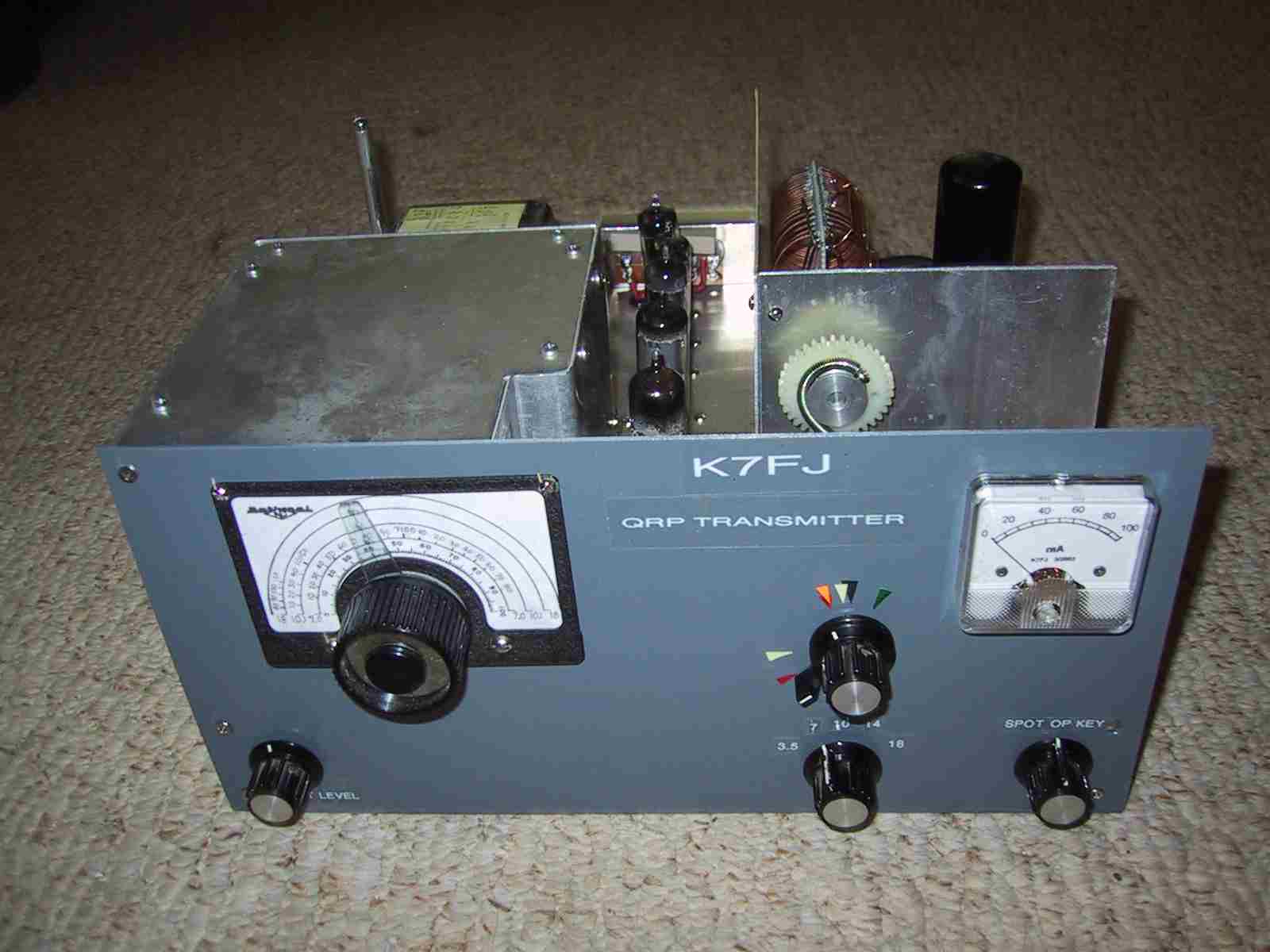
The new QRP rig is finished. It has replaced the little QRP-VFO rig shown in QST (Jan 2003 p83), performing essentially the same as that little rig (shown also in my shack photos) but is much larger and more carefully built. The new rig covers 80 - 17 meters CW and has a 6L6 final instead of the 5763 used in the original. It now also includes a built in power supply and is used along with the Ultimate Regen or SX28A receivers.
Tube lineup is 6AU6 vfo, 6U8 cathode-follower buffer and multiplier, 5763 multiplier, 6L6 final. The circuit design is fairly conventional except for:
1) The vfo is oscillating all of the time but does not interfere with the receiver because a reed relay responds to the key and switches a small capacitor in the tuned grid circuit. This relay is controlled by a transistor circuit and operates from a 5 volt power supply derived from the oscillator filament supply. When not keyed the oscillator runs 100 khz or so lower than it does when transmitting.
2) The bandswitching is very complex and is possible only because I had a complete bandswitch assembly removed from and old Tempo-1 transceiver. The same old Tempo-1 provided a concentric shaft control mechanism to operate both final tuning and loading controls. (The loading control is a ring around the tuning know on the front panel.)
3) The 6L6 final runs in class AB1 with fixed negative bias. This allows the keying to be shaped in the lower level driver which is much easier to control and is independent of final tuning.
4) The vfo oscillator runs with only about 5 volts to the filament and this is provided by a seperate transformer so that filament voltage is not affected at all by loading of power circuits during transmit. The independent filament supply is essential to prevent frequency drift while transmitting that is otherwise caused by slight changes in oscillator filament voltage from the main power transformer powering the high level circuits in the transmitter. The reduced filament voltage together with low plate and screen voltages were chosen to reduce oscillator tube heating without significant sacrifice in output level. This results in lowest possible drift.
5) The vfo oscillator has the plate tuned at a multiple of the oscillator frequency. In my design I use tuned circuits in the oscillator plate to improve both output amplitude and waveshape typically provided by untuned vfo oscillators. However, this can lead to vfo instability if the plate is tuned to the same frequency as the grid so I found I had to tune the plate to a multiple of the grid frequency, effectively using the vfo as my first stage of multiplier.
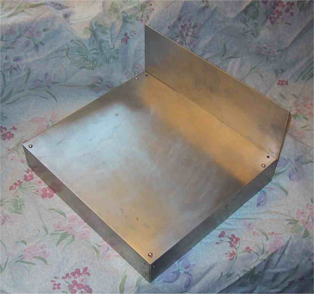
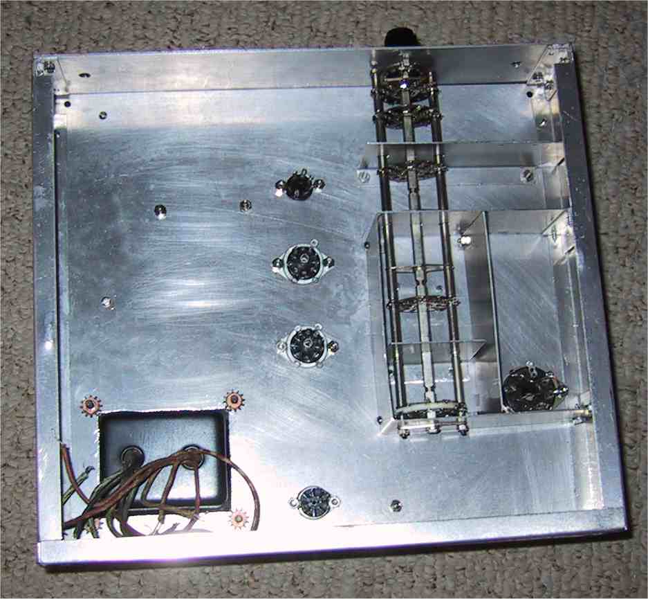
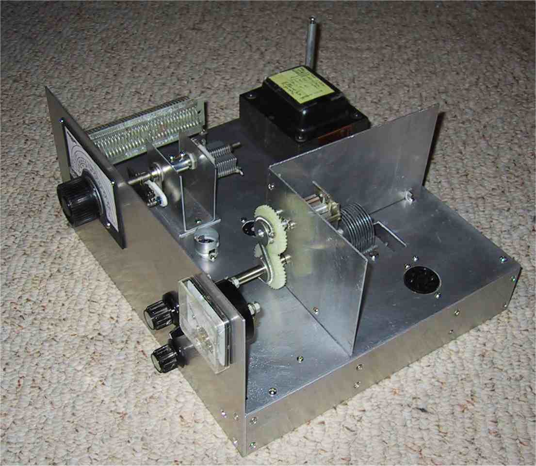
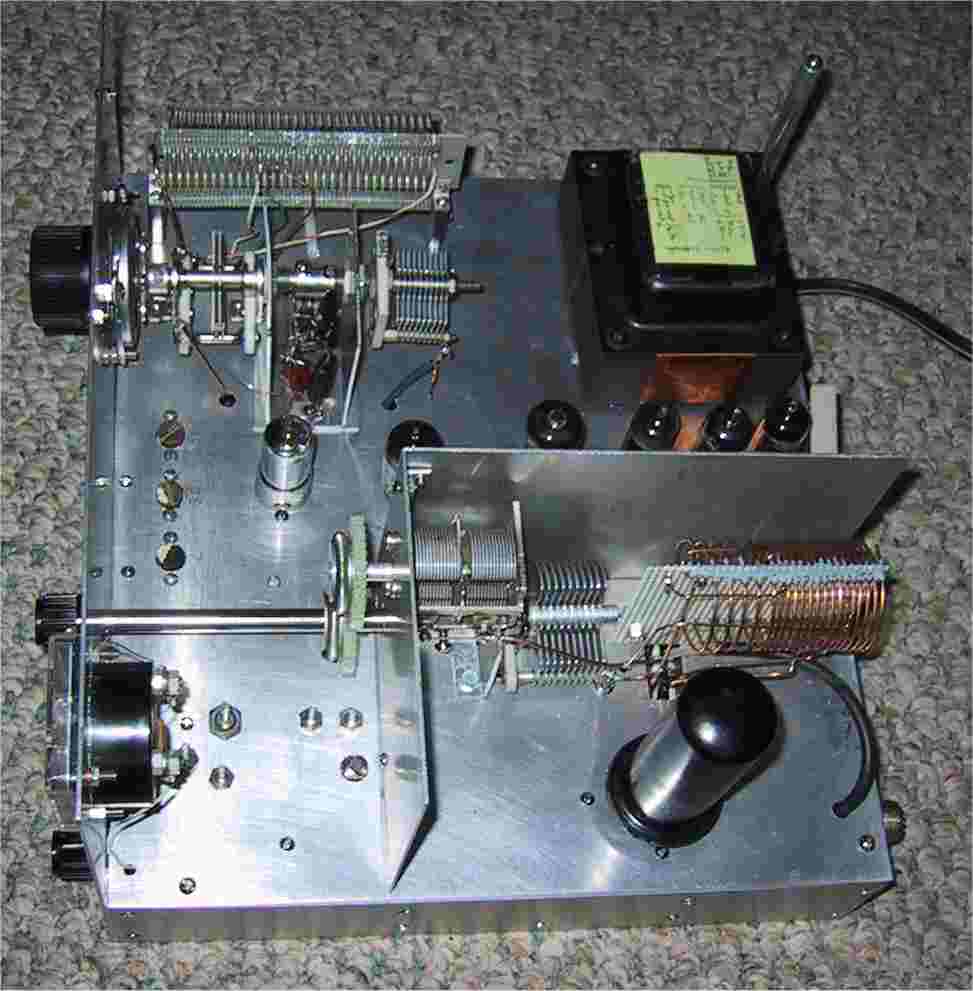
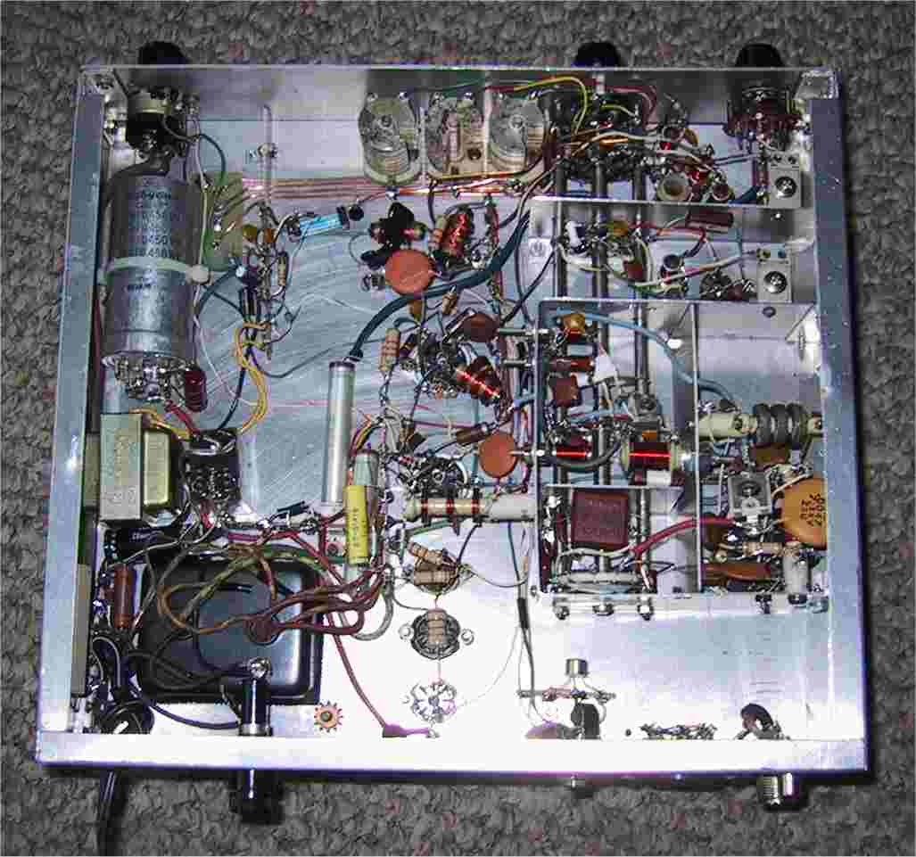
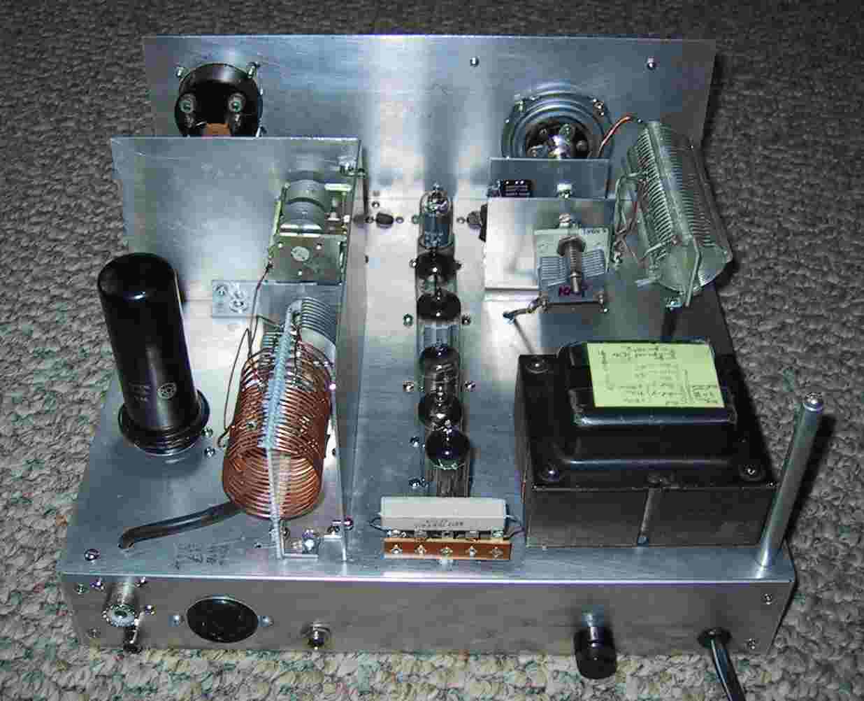
The homemade chassis is in the two views to the left. I have never thought it was worth all the cutting, filing, and bending just to save a few dollars but I have the scrap aluminum and a lot of time. The view to the right shows most of the major components installed. Previous projects have often suffered for lack of adaquate shielding and seperation and so on this one I have taken shielded compartments to the extreme. The photos below show the completed rig. VFO compartment cover is removed in last 3 pictures.
 BACK TO HOME PAGE
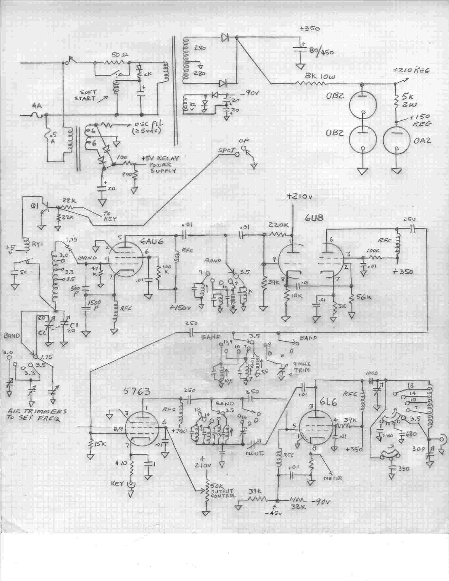 SCHEMATIC