 |
|
A simple and convient to use control box for mobile HF operation. |
|
|
|
A simple and convient to use control box for mobile HF operation. |
Due to popular demand, in this page I am documenting the construction of a control box I built to operate my ATAS 100 HF Mobile Screwdriver antenna. I had purchased this antenna and a control box to go with it from AmCom. I connected it to the tuner port of my Icom IC-706 since it provided a convenient source of 12V power. It was then I discovered some shortcomings of the AmCom tuning control. Inadvertently, the coax going to my antenna became shorted, and there is no DC fault protection in the AmCom unit. Not only did it cause the AmCom unit to fail, but it burned the power trace in the 706 at the same time. Not wanting this to happen again, I came up with my own improvments and additions and this is the end result.
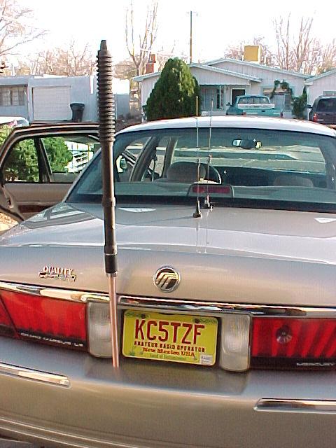
I purchased this unit since it was more appealing to the XYL (since it was going on her car...). Since any loaded HF mobile antenna is typically pretty inefficient, the notion of running a High Sierra or Tarheel antenna for a couple percentage point improvement didn't seem worth the expense or large size. I'm not a serious HF mobile operator anyway, so absolute performance wasn't a big factor. I was suprised to see the small-gauge wire that comprised the loading coil, but was impressed that they wound it using a variable pitch. The construction of the antenna seems very good, with excellent fit and finish. I really like the idea that it is tuned by applying a positive DC voltage through the feedline, eliminating the need to run a separate cable to the passenger compartment. I'm not crazy about the PL-259 mount, but given the thick base section I doubt it will ever give me any mechanical problems. I don't like them because the mounts tend to collect water and corrode, and aren't meaty enough to deal with the stress. To solve that problem I built my own extension mount out of copper water pipe.
 |
 |
|
|
extension is put together. |
The minimum SWR frequency range of my ATAS antenna in the vehicle was 6.78 MHz up to 48.8 MHz, (1.2:[email protected]) per my MFJ-259B antenna analyzer. The DC used to control it I measured per the following table:
|
||||
| DOWN | UP | |||
|---|---|---|---|---|
| Min | 4.8 | 10.0 | ||
| Max | 8.5 | 14.4* | ||
| Nominal Current Run/Stall, mA |
165/540 |
185/550 |
||
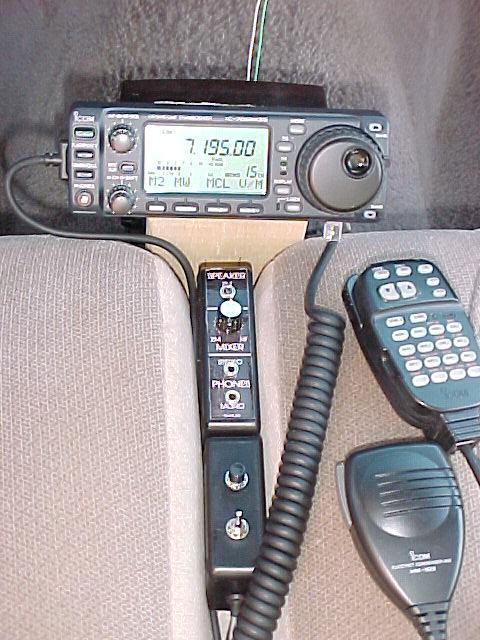
The concept of this unit is very simple. The Yaesu ATAS 100 antenna is tuned through it's feedline instead of a separate control wire. 12VDC applied to the feedline lengthens the antenna, 8VDC shortens it. The control box isolates the control DC from the radio with a blocking capacitor, and isolates the RF from the control box with an RF choke. 3-terminal regulators provide the control voltages to the antenna, as well as providing current-limiting fault protection. These regulators won't source more than about 1.5A or so, no matter what the load. Since I was connecting the control box to the Icom's tuner port for 12V power already, it was a trivial effort to connect and bias the pins correctly to enable an external 'Tune' pushbutton. Adding a connector to extend the up/down and tune pushbuttons gives the option to route the controls remotely with the control head, or operate the antenna at the transceiver.
Click the image above for a full size schematic.
 |
 |
|
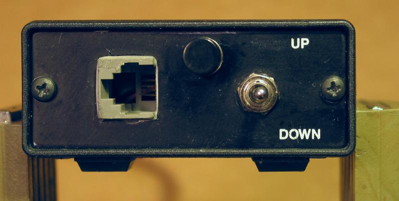
The lower box is the remote control that plugs into the ATAS control box via 4-wire telephone cable. |
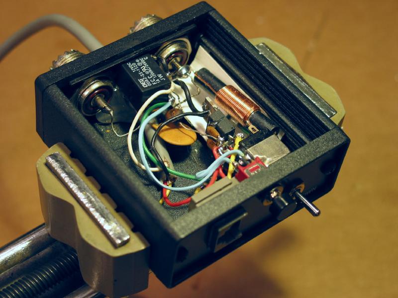
I built this unit in the case the Am-Com unit was built in. the only original parts are the high voltage coupling capacitor and connectors. |
Operation is very straightforward. Adjust the up/down switch to peak received signal strength. This peak is most pronounced on lower frequencies but is still readily detectable up through 10 meters. Once peaked, the TUNE pushbutton is pressed and the up/down switch is 'bumped' to achieve minimum SWR as indicated on the 706's built-in SWR meter. Once you have a knack for this process, quite often the antenna needs very little adjustment from the peaked receive position, usually it's within one or two 'bumps' up or down from optimum.
I really get a kick out of HF mobile operation, and having a remotely operated screwdriver antenna really enhances the enjoyment and convenience. This remote box isn't as convenient as some of the automatic ones on the market but for what it costs to build one, is still a useful mobile operating accessory.

Project Page |

Home Page |
