EV Charger
ALL PHOTOS ARE CLICKABLE
FOR A LARGER VIEW.
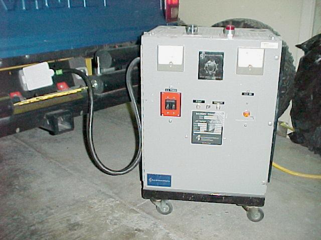
FrankenLester.
by
Mark Brueggemann
Albuquerque, NM
This circuit uses the DC current present on the output of the charger transformer to close a senstive reed relay. In high-current conditions (during charging) a strong magnetic field keeps the the reed closed, and the circuit active. As the current tapers off towards the end of the charge cycle, the magnetic field diminishes proportionally. When it reaches a level that will no longer keep the reed closed, the circuit will deactivate the control contactor to the charger transformer, stopping the charge cycle. The current level at which the circuit deactivates is determined by the number of turns used on the sensor coil, and how much of the reed element is inserted into the coil. Thus, by changing the number of turns and the amount of coupling to the sensor coil, the exact current level at which the circuit deactivates may be controlled.
 |
 |
|
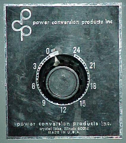
to charge uncontrolled. |
control set for about 6 amps. |
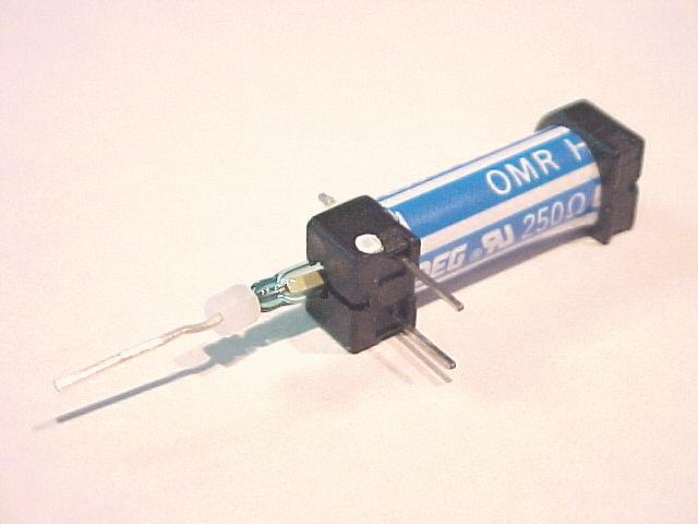
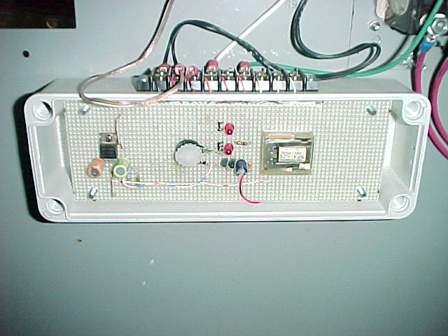
None of the parts on this schematic (GIF or PDF) are critical, just about any equivalent part may be substituted. The only thing to consider is that the main switching transistor Q1 must have enough current capability to close the contactor control relay RY2. If you use all the Radio Shack parts outlined on the Bill of Materials , the circuit will work exactly as advertised. The reed is removed from the relay coil by bending the leads on the ends of the relay body straight out, then *gently* pulling the reed out of the end that has the white spacer in it. This glass reed is very fragile, I ended up breaking a couple of them until I finally encased one in epoxy resin. If you're careful, you can get away with just using silicone seal in it's final mounting position inside the sensing coil. If you think you'll be experimenting, you're better off encasing it in a protective package.
 |
 |
|
pull will remove the reed element from the coil. |
resin, and inserted into the pickup coil. |
 To test the circuit once you're done building it, power it up with a
bench supply, battery, or wall wart, and short across the reed relay
using S3. The LED will light and RY2 should close. Open S3 and the reed
and the relay will open. A magnet near the reed element should do the
same thing. That's all there is to it, when combined with the contactor
in the charger it will stay latched as long as there's enough current
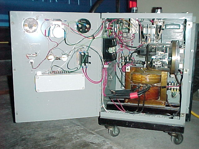
through the sensing loop to keep the reed closed. The charger sensor
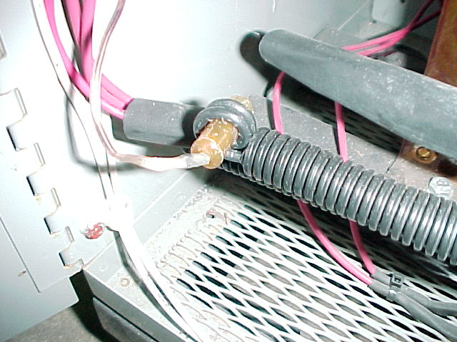
coil is made by locating the center tap lead of the main output
transformer secondary (in the case of a Lester), or using either the
main positive or negative lead (of a regular charger). With my Lester,
two 1/2" diameter turns of 10ga wire is enough to keep the reed closed
all the way down to about 3.5A.
To test the circuit once you're done building it, power it up with a
bench supply, battery, or wall wart, and short across the reed relay
using S3. The LED will light and RY2 should close. Open S3 and the reed
and the relay will open. A magnet near the reed element should do the
same thing. That's all there is to it, when combined with the contactor
in the charger it will stay latched as long as there's enough current
through the sensing loop to keep the reed closed. The charger sensor
coil is made by locating the center tap lead of the main output
transformer secondary (in the case of a Lester), or using either the
main positive or negative lead (of a regular charger). With my Lester,
two 1/2" diameter turns of 10ga wire is enough to keep the reed closed
all the way down to about 3.5A. 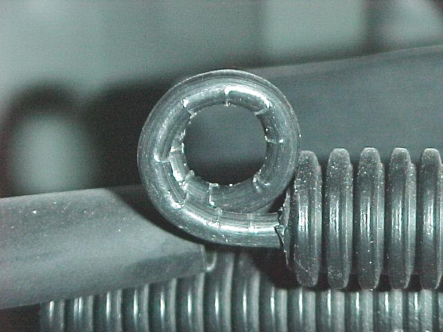 Other chargers and currents may need more or less turns depending on
the current being used. You want the minimum number of turns it takes
to keep the reed closed at the smallest amount of current you want to
sense. This is to give you adjustability for a higher current setting
by moving the reed out of the coil. There was enough existing wire in
my charger that I was able to create the two-turn coil without having
to splice into anything, which is another nice aspect of this circuit-
no modifications to the high-voltage wiring. Once you have the coil
wound, just use a tie-wrap or two to keep it's shape. Connect RY2 and
start/stop switch connections to the main control contactor in the
charger, and you're
ready to test and calibrate the unit.
Other chargers and currents may need more or less turns depending on
the current being used. You want the minimum number of turns it takes
to keep the reed closed at the smallest amount of current you want to
sense. This is to give you adjustability for a higher current setting
by moving the reed out of the coil. There was enough existing wire in
my charger that I was able to create the two-turn coil without having
to splice into anything, which is another nice aspect of this circuit-
no modifications to the high-voltage wiring. Once you have the coil
wound, just use a tie-wrap or two to keep it's shape. Connect RY2 and
start/stop switch connections to the main control contactor in the
charger, and you're
ready to test and calibrate the unit.
Operation
Operation is as simple as connecting the charger to the EV and pressing the Start button, S1. It will stop on it's own as soon as the charge current drops to the predermined setpoint, or if you press the Stop button S2. Adjustment of the reed coupling is accomplished as follows. Insert the reed so that it is centered inside the sensor coil. Start the charger and monitor the current as the batteries charge. Once the batteries have reached the state of charge you want and the current has tapered down, slowly pull the reed element out of the sensor coil until the charger stops. Re-verify this is the point you want by waiting a minute and starting the charger again, and watching the current. It will ramp down quickly this time since the batteries are already charged, and should shut off when reaching your current setpoint. To shut off at a higher current move the reed out of the coil, at a lower current move it into the coil. I found that once the reed is set it is very consistent and did not require any further adjustment after initially setting it up. Once you find the spot you like, use silicone sealant to keep it in place. For purposes of equalizing or testing, S3 is included so that the charger will activate and stay activated no matter how much current is present.
 |
 |
|
durable and unmistakable as to function. |
after the reed circuit senses a charged pack. |
This circuit would be the bare minimum control you would need for a simple EV charger. However, it doesn't take much to make it a bit more useful. In my case I use the control circuit to not only shut the charger off during a daily charge, it can activate a manual timer to perform an automatic equalizing charge. I also added an interlock circuit between my EV and the charger so it won't activate unless plugged into the truck. This circuit has been in use since January 1999 and hasn't hiccupped once, and only took me a couple of hours to whip up. As a replacement to a failed Lester timer board or a main control for a home made charger, it doesn't get much simpler or more reliable. You could throw a microcontroller and a lot of money at this problem, but for the bulk of EV owners out there, this circuit is just the ticket.

Main Page |

Home Page |
