Heathkit SB-104, HW-104, SB-104A Transceiver Repair
Heathkit SB-104, HW-104, SB-104A Transceiver Repair
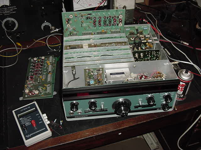
The purpose of this Web Site is to help you bring those Heathkit SB/HW104s back to life. There are other excellent Heathkit web sites which have all the SB-104(A) and HW-104 Service Bulletins and Fixes listed, such as:
This web site is to help you debug "the unit in front of you" and grew out of input from others and my personal experiences debugging a few I bought (one of which turned out to be a "collection of bad boards"....... quite an education). My sample size is relatively small and I didn't work at Heathkit, but some of this info may be helpful to you. Bottom line is, while they do require some TLC, they are good transceivers, a part of Heathkit history, and will provide many more hours of fun.
I want to thank Ed Mosher (WA8ZVO), David Kechkaylo (W8DLK), Mike Bryce (WB8VGE), and Benton Allen (WB5TWC) for providing schematic information and suggestions while I was/am going through these transceivers.
One of the most helpful items was being able to use a SB-104A schematic that was marked up with the proper voltage levels and used by the Technicians at Heathkit. The schematic is now available online as a 1.5Meg ".pdf" file. If you don't have a ".pdf" reader, you can download Adobe Acrobat Reader 4.0 (free) off the internet.
The SB-104A Tech Schematic file is located at SB-104A Schematic. When you "right click" on the SB-104.PDF file with Internet Explorer, you can do a "Save Target As...." and put it in a folder, the desktop, etc. If you "left click" it will download to your computer for immediate viewing. Since this is a ".pdf" file, and you can't then do a "save as...." with Adobe Acrobat Reader 3.0. What you do is go to where the file is stored on your computer.... do a "Find" of files or folders for "Temporary Internet" and click on that. You should see the SB-104 file and be able to drag it to your desktop, another folder, etc. Have fun, it's a very useful schematic and Adobe will allow you to zoom in and out.
A copy of SBM-104-1 and SBM-104-2 are available from me for $10 postpaid in the US and Canada or $12US postpaid worldwide. SBM-104-1 is the instruction set which came with the Modification Kit to improve the sensitivity of the receive section of your Model SB-104 SSB Transceiver ("G" board). SBM-104-2 is the instruction set which came with the Modification Kit to update your SB-104 to the SB-104A. This is a useful item to distinguish between SB-104 and SB-104A level boards since they were/are often swapped.
As usual, I welcome additional input and corrections. Please send them to
[email protected]
..........73s Kees K5BCQ.
BACKGROUND
IMPROVEMENT BEYOND REPAIR
TOOLS YOU WILL NEED
REPAIR BASICS
POWER SUPPLY
DEBUG - GENERAL
"A" Board - FREQUENCY COUNTER (DISPLAY, DC CONVERTER)BACKGROUND
"B" Board - TRANSMITTER AUDIO/REG
"C" Board - TRANSMITTER IF/PREDRIVER
"D" Board - HFO/PREMIX
"E" Board - CARRIER GENERATOR
"F" Board - RECEIVER IF/AUDIO/AGC
"G" Board - RECEIVER FRONT END
NOISE BLANKER Board
"H" Board - POWER AMPLIFIER
"J" Board - DRIVER
"K" Board - FILTER/ALC
Misc Card - OSCILLATOR
Misc Card - BUFFER
Misc Card - VFO FILTER
The SB-104, HW-104, and SB-104A have some differences, the most obvious being that the HW-104 has an analog frequency readout vs the digital frequency display of the SB-104 and SB-104A (and has a few less "birdies" as a result). The HW-104 uses less expensive phenolic PC boards vs the glass boards of the SB-104 and SB-104A. The HW-104 has a crystal calibrator option, which the SB-104(A)s don't need due to the inherent accuracy of the digital readout, once calibrated with WWV. All these units have a CW Filter and Noise Blanker option. To further reduce costs, the HW-104 came with one 10m segment (500Khz) and had a "full 10m coverage" option.
According to Chuck Penson's book, the SB-104 came out in 1974 followed by the HW-104 in 1975 and were both produced until 1977. The SB-104A came out in 1977, was produced until 1982, and is a much improved design version of the SB-104 incorporating most of the available critical fixes. I think production figures would be interesting, but from what I've seen there are plenty out there......and many of them need some work. I'm told that Heathkit always reworked units returned for servicing to the latest level, so if you have a unit serviced by Heathkit, the chances are that the fixes have been implemented.
NOTE: These are "fixes" to make the transceivers function better. If your unit does not receive, transmit, display, etc...there is a problem that needs to be repaired ...first. Installing any "fixes" at this time would only complicate matters.
It is still Heathkit's first fully Solid State HF Transceiver, it was leading
edge technology at the time and broke much new ground for solid state HF
transceivers, it's a part of history, it can be made to work very well
....and contrary to rumor, it's a very straight forward design and was/is not
really a complex kit to build (a credit to the Engineers at Heathkit and the
design groundrules/guidelines they worked under).
Very often you see SB-104(A)s (and other older transceivers) advertised as
"not working", "has low output", as "parts only" radios, or see them on e-Bay
with "works great" and "16603.6 Mhz" shown as the frequency.....sure "it
works". These are generally
simple problems to fix. Often people believe "the hard to find (true) finals
are shot", but I've only found one case where that turned out to be the
problem. Most of the time it was out of alignment, some other (cheap)
component was defective, a bad solder joint, etc. Besides, "IF" the finals are
bad they can be replaced with similar components which are more readily
available today.
In addition to the fixes published by Heath, there were several excellent articles on improving the SB-104 receiver in ham magazines. Some were published as late as 1998, which demonstrates how "Fellow Greenies" want to keep these rigs on the air.
An improvement is to replace the relay (if it's causing problems) with a plug-in unit. With a "nibbler" tool you can enlarge the hole slightly and mount a socket. Today we have access to excellent gold contact plug-in relays (such as Potter Brumfield R10-E4-X6- S320 12vDC) with more than adequate current/voltage ratings.
Some may want to replace the "Ant" RCA phono plug with a round "bulkhead" mount BNC connector. They fit nicely and provide an excellent, solid, 50 ohm antenna connection. The RCA is also an excellent 50 ohm connector system at 100 watts (better electrically than the old PL-259 UHF connector system) but after many years the ceramic insert starts to chip and deteriorate through use (compare it to the other RCA connectors). Also, one of the causes of problems in a SB-104(A) is that the internal RCA connectors come loose, oxidize, etc .....pointed out in the Heathkit manual. RCA connectors are not real good for mechanical retention, especially where the cables are stressed as they exit the unit. The BNC connector system is an excellent, low power, 50 ohm system ....both electrically AND mechanically (and convenient). The only drawback is power handling capability, but if you look at the airgaps, insulator thicknesses, insulator material, and plating materials used, you will find them superior. I've never had a problem with around 100 watts. A BULKHEAD mount BNC connector does NOT modify the chassis. Remove the RCA connector and install a bulkhead BNC, which has a small threaded barrel on the back, with the nut provided. The diameter of the threaded portion is actually smaller than the RCA connector and it goes through the hole with plenty of room to spare.
Changing the mic connector from 2 pin to 4 pin is personal preference. Both
types of connectors are readily available today from various vendors, so
don't replace a 2 pin connector just because you can't find a 2-pin plug.
A good set of head magnifiers comes in handy unless you happen to have very good eyes.
A schematic for the particular transceiver you have is mandatory, as is the Operations Manual. The Assembly Manual is not required but you may find it useful. Manuals are available from individuals on e-Bay, the HEATH reflector, and from various manual vendors like Al Bernard ([email protected]).
An extender card, or some other means of gaining access to probe points on the cards, is also mandatory. If you can't find or borrow an extender card, you can "tack solder" probe wires (insulated) to the specific points being tested and reinsert the card. This is also useful since it puts the boards in their operating environment since use of the extender card can cause oscillations due to unshielded coupling to other boards and the longer lead lengths. In particular, this can be seen when board C is on an extender or when two boards F and H, F and G are on extenders. There has also been discussion on the HEATH reflector of "new production" extender cards.
In addition to a good Oscilloscope, DMM or VTVM, Frequency Counter, and Signal
Generator, an Audio VTVM (with a meter) is handy for measuring receiver
sensitivity. The mechanical meter is required to dampen out fluctuations
for accurate adjustment. Another great tool is a "cheapo" 2K ohms per
volt VOM for checking diodes and transistors. Most of the suspect transistors
and diodes can be readily pulled for measurement. For the PA transistors, the
easiest method is to cut the appropriate trace(s) with an X-acto knife, make
the measurements, and resolder the trace. Many of these devices are paralleled
with other components and can not be tested "in place".
Don't start by powering the unit up as your first step. Something could have been knocked loose due to shipping/transport. Also, since these are kits, don't automatically assume they worked at one (or any) time. I can't stress this last point enough because it's not part of normal commercial receiver debug. I have found missing components, incorrectly installed components, solder blobs shorting board traces, and wrong value components installed ....and more. The point is, don't automatically assume a complex kit is wired correctly even if you were told "worked great the last time I used it" by the previous owner/seller.
Make sure the VFO jumper is installed (between VFO OUT and VFO IN) on the rear of the unit and that the Accessory Plug has the pin 2 to pin 5 jumper.
The 11 pin POWER plug on the back is used to bring power from the power supply or car battery. Pins 7, 8, 9, 10 are negative ground. Pins 11, 1, 2, 3 bring positive 13.6 VDC to the finals (ONLY). Pin 4 brings 13.6 VDC to the rest of the circuits. There have been "Transmit does not work" problems reported because only pin 4 was wired to 13.6 VDC. Pins 5 and 6 are used to switch power on and off in the power supply if your external supply is so equiped. The Heathkit SB-104(A) supply is so equiped.
A visual inspection (and cleaning) is a good place to start. Use plenty of DeoxIT (CAIG Labs) for cleaning the switches and card contacts which will all oxidize over time ....intermittents are difficult to trace. You may also find it useful to bend one or more of the three small spring fingers on each contact a little to make more reliable contact with the chassis mounted pins. The pins oxidize over time and I have seen the pins coated with grease to reduce oxidation. I don't see anything wrong with that, but prefer bending the contacts a little.
Since their introduction in 1974, it's fair to assume they have all been worked on some, by Heath, by individuals, in repair shops, etc. Because of this and the ease of swapping plug-in cards, a SB-104A you have may include cards from SB-104s and HW-104s .....mine did. Point is, just because it says "SB-104A" on the front, doesn't mean that everything inside is "SB-104A".
It's a good idea to look down from the top of the unit to check if any wires or components are touching the aluminum partitions or the card guides on the sides. There are some inductors on the "C" board which come really close and a little bending/placement can save you a lot of problems.
There will definitely be a variation from unit to unit depending on the fixes installed and they should be used as guidelines. If you expect to see 200mv and see 160mv, no problem. On the other hand, if you see 10mv, there is a problem.
Relative to the schematic:
Don't go to full power without a properly matched antenna or dummy load.
The "Tune" position is for adjusting the antenna tuner, etc (and for QRP
operation) before applying full power. The output transistors don't take
"key down" operation into a mismatched load for very long and they are
expensive to replace. The ALC will NOT provide full protection.
You will need a good 12VDC 20Amp power supply, either the
Heathkit HP-1144 or something else with the correct 11 pin connector. Let
me state at this point to NOT "rig something up" for the connector. SB-104(A)s
do NOT have reverse voltage protection (usually a large diode which is
normally reverse biased) like some other units have. If you momentarily reverse
the power you will probably take out the regulators and Q207 on the "G" board
...and more. A protection diode is a good item to add to your SB-104(A).
The SB-104(A) draws roughly 3 Amps in receive, 5 Amps in Low Power transmit
and close to 20 Amps peak in High Power transmit.
The easiest (and quickest) method of unit debug, by far, is to debug at a higher level and substitute known good boards which is why so many SB-104(A) owners have a "spare". Computer manufacturers discovered that a long time ago. But this is the home environment, down time is not mission critical, and some can not afford the cost of board level replacement. Someone is going to have to debug those bad boards......you.
Use the Troubleshooting Charts supplied by Heathkit in the Operations Manual as a starting point. There is a sequence to debug which seems to work best: check power first and recheck it at every card being debugged, then get the receiver to work starting with any noise from the speaker and working back to the antenna, then work on the transmitter starting at the VFO and work toward the antenna.
When I powered on my first SB-104A all that happened was the 2 pilot lights came on and the meter would read 13.8VDC.....everything else was dead. No display, no noise, no Tx relay picking, no S-meter reading, nothing....that's a pretty slow start. But, on the other hand, no excessive current draw or smoke.....and that's good.
Several of the "needs work" SB-104s say that they have "low power output" with an implication that the PA "H" board transistors may be fried. I've only seen one which actually had 2 of the 4 transistors bad, the others were an open RF choke on the Driver "J" board and not enough drive from the HFO/Premix "D" board into pin 10 of the TX/IF "C" board or not enough drive from the Carrier Generator "E" board into pin 3 of the TX/IF "C" board, etc.
Intermittent problems can often be traced to defective solder joints. When in doubt, reheat the joint and apply a little solder. If there is a large qty of solder already, wick it off or use a "solder sucker" and renew it. Several times, I've wiggled a component only to see the lead move slightly in what looked like a good solder joint. It's time consuming to systematically check all the solder joints, but the vast majority of kit problems are traced to defective joints. It's also good to hold the cards against a strong light and check for solder bridging, scratching a little flux off here and there with an X-acto knife and an old toothbrush to see more clearly. On boards with "similar" band circuits, such as the "D" board, it's sometimes easier to spot solder bridging.
Grounds (signal return paths as well as shielding) are as important as the signal wiring and all ground points should be examined to make sure they make good electrical contact. The card side rails are important for proper operation and the minimizing of spurious signals. Some boards have been removed so often they have worn through the solder covered traces on the sides. I have added copper tape to these boards to maintain electrical contact. Also check any mounting screws for good contact on the Noise Blanker card, Driver board, etc.
The later SB-104As used film resistors (shiny, "dog bone" shaped) which are typically more stable over time than the older composition resistors (dull, cylindrical). Many of the older composition resistors, through age and moisture intrusion, will change value so check when they are suspect.....gold 5% tolerance band or not.
Stiff tuning can often be fixed by relubricating the ball vernier drives. Even the Jackson Bros vernier drives (especially old ones) develop something other than smooth tuning due to hardened lubricant, dirt, dust, etc (feel a slight grinding, backlash, etc). Taking them apart for cleaning and making sure the correct pressure is applied to the 4 balls requires care, since those six "fold-over" tabs control tension via the bronze "waffle spring/washer" and are not meant to be mashed tight. Too tight will result in stiff tuning, too loose will result in slipping. But it does allow you to completely clean the drive assembly. Soaking in solvent works to some degree. A much easier way, which works well, is to heat the body of the vernier with your soldering iron (reflows the grease). If you need more grease use automotive lithium chassis grease or Lubriplate. To force the grease into the bearings, fill the coupling with grease and, with the set screws in place, hydraulically force the grease inside using a section of 1/4" dia shaft until you see it exiting around the input shaft.
Intermittent potentiometers or those with "stiff" adjustment can often
be fixed by spraying with a little DeoxIT (CAIG Labs) or in the case of stiff
adjustment, also remove the knob and spray the bushing.
Same goes for switches, plugs, sockets, etc.
The display on the SB-104 and SB-104A is driven by the +5v supply
through a DC-DC converter that has an output of +180v. If the transceiver
shows 6,60xMhz, 16,60xMhz, or 26,60xMhz depending on the position of
the bandswitch but tuning has no effect, chances are that the +11v supply
is defective. Check the voltages at the "B" board and the pass transistors.
The DM8880 ICs are still available from places like
Athena Electronics.
This board apparently has problems often because it sees the +13.8v first
and the regulators (IC202 and IC203) are very sensitive to voltage swings.
On my first SB-104A the +11V power supply measured +3V and the +5V power supply
measured 0V. After measuring the correct +13.8V at pin 2 of the "B" board and
NOT measuring about +11V on pin 3, nor about +5V on pin 5 of the B Board (drives
the base of the pass transistors), it was determined that both regulators
(IC202 and IC203) were bad (probably due to a +13.8v power supply reversal
at some time). These regulators are somewhat difficult to find but there are
alternatives. If you have exhausted parts
sources for the original MFC6030, you might try substituting the UA78MG or
take a more drastic step of redesigning the regulator circuit. I wanted
adjustment capability so, replaced the on board regulators with LM-317
units and redesigned the circuit to use PNP pass transistors and multi-turn
adjustment potentiometers on the top of the "B" Board. This has advantages
of full screwdriver adjustment and you can't accidentally change the
setting. You can use the existing NPN pass transistors, but you loose control
over the voltage drop across the pass transistor....see the ARRL Radio Handbook.
NOTE: Always set up the adjustable voltage regulator board for correct output on the bench ....or unplug all the other boards. After the +5v and +11v levels are OK, plug in the other boards and readjust the levels if needed.
A second SB-104A showed 6,603.6Mhz, 16,603.6Mhz, or 26,603.6Mhz depending on the bandswitch setting with VFO tuning having no effect. Also no audio. This was due to a defective +11v regulator (IC203). The apparent cause was the case of C6 shorting to the +13.8v on the pass transistor (the plastic insulation sleeve on the electrolytic capacitor can crack and make contact). The short burned through the negative lead on C6 and the surges probably took out the regulator.
In both above instances the T/R Relay transistor (Q207) was toast. A defective Q207 which allows 5 or 6 volts on pin 6 of the "B" board in receive mode, will effectively bias the audio off (pin 7 of the "F" board). There are suggested substitutions for this PNP transistor (2N3906, etc) or you might go with a higher current substitute like a Radio Shack 276-2026 transistor as indicated in the N2EO article (and reduce the value of R217 from 4.7K ohms to 2.2K ohms).
Audio voltages: for 1Khz 150mV P-P input at the mic (pin 16) you should
see 8V P-P at pin 5 of IC201A. With the Mic gain set at ALC threshold in
Low Power you should see 30mV P-P at pin 3 of IC201B, 2.5V P-P at pin 4 of
IC201B, .6V P-P at the emitter of Q201 and BAL-MOD of the card (pin 11).
Same thing applies here to the mixer diodes as on the "G" board.
Make sure the spring fingers over the 10m coils make good contact with the metal partitions.
Check the band select switching levels for proper individual switching. If not correct (due to a solder bridge, for example) you may have multiple tuned circuits selected simultaneously.
Don't worry about output signal quality at this point in the circuit if you are using a scope. It's not a nice sine wave.
The little silicon switching diodes are pretty sturdy and don't fail often. If you need to replace one, use a common 1N914. Do not use 1N914s for any of the mixers or any signal diodes.
I have found a defective D310, D311, and D312 so check the bias levels on Q304 and Q305 carefully. One diode (D312) was intermittent. Apparently one lead had actually come loose in the glass.
The Input voltage (pin 3) should be .3VRF +/-.1VRF.
The injection level (pin 10) should be around .4-.5VRF for 80m, 40m, and 20m and .3-.4VRF for 15m and .2 for 10m.
The RF OUT (pin 24), with Mic/CW level FCW, should be about .6VRF for 10m and 15m, .7VRF for 20m and 40m and 1.6VRF for 80m.
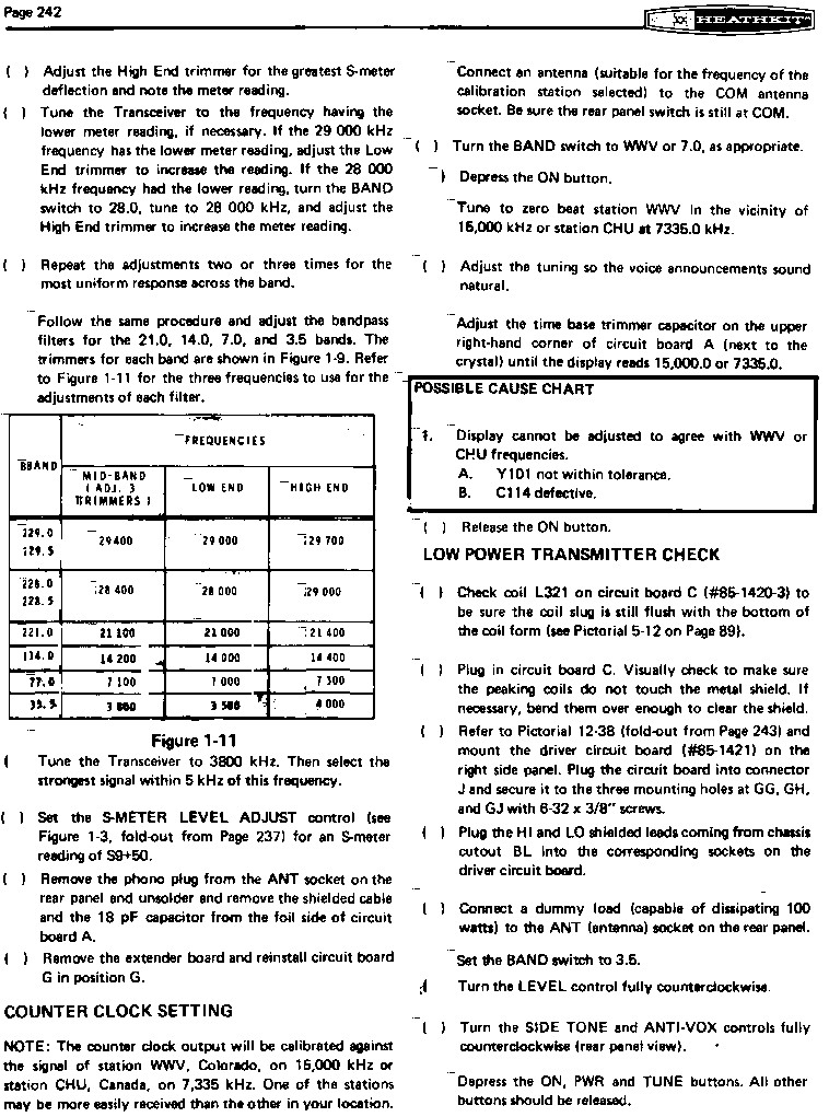
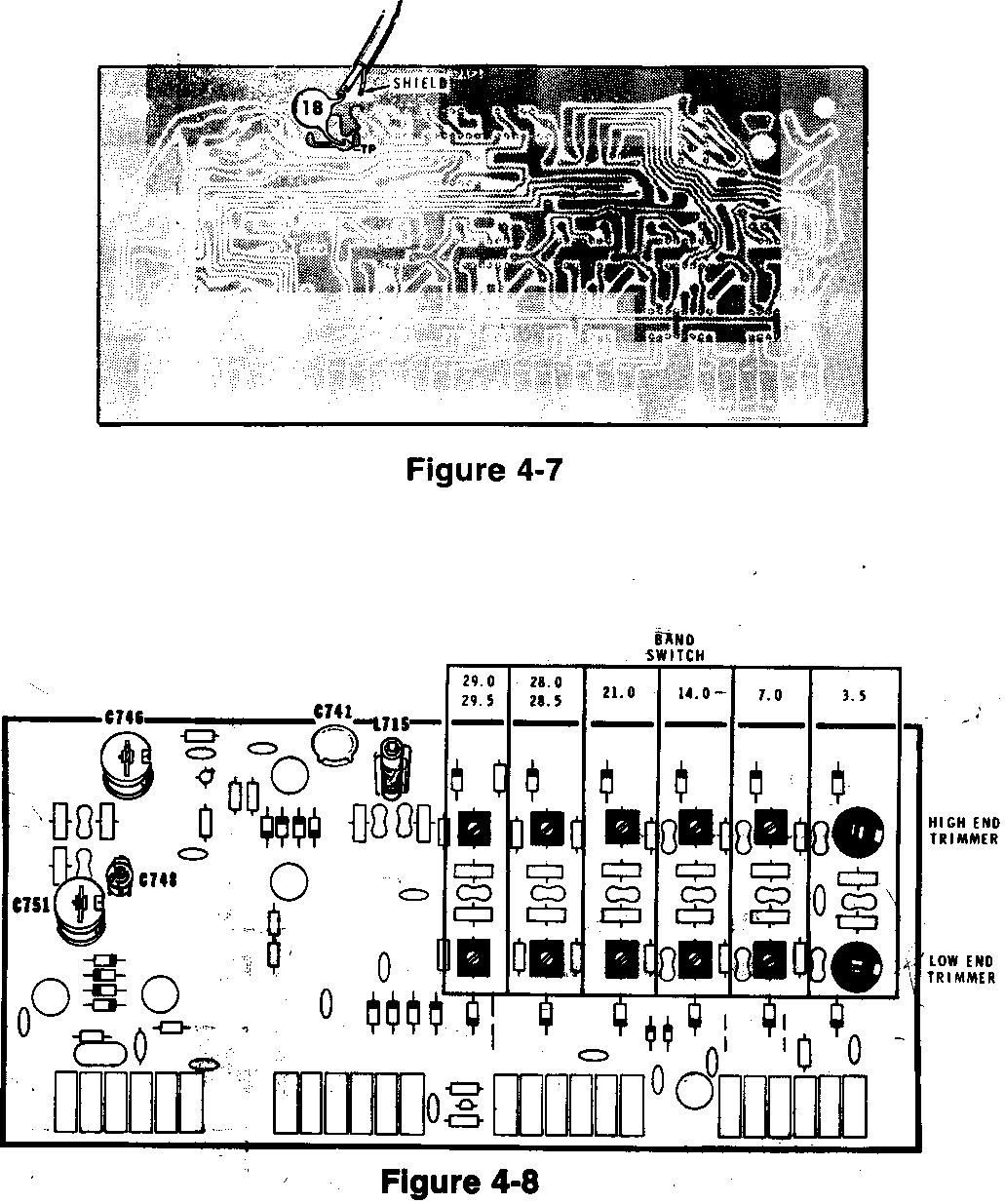
The 15m and 20m filter sections on the SB-104 were wider. On the SB-104A,
they were narrowed to reduce spurs but this required tuning of the filters to
provide adequate levels across the entire band. For 15m, the change was:
C333 a 3.5-18pf trimmer and C332 to 50pf. For 20m, the change was C337 a
8-20pf? trimmer. C336 remained 220pf.
You can follow the procedures in the manual and look at the test point or connect a scope to "HFO OUT" pin 2 and make measurements. The slugs should have two peaks, one with the slug "out" and one with the slug "in". Use the "in" position for your adjustment. Make your final adjustment to the "non sharp rolloff" side of the peak. If a specific coil has a single peak, it may be out of the adjustment range of the inductor and, you may have to change some parallel mica capacitor values to allow the slug to tune correctly (parts change over time).
Check the coils for shorts since some of the leads to the inductor terminals are tight against the windings (found one of those shorts).
If a particular band has no output and you have checked the components and the wiring for shorts and bridges, and it's finally down to suspecting the crystal, you might try substituting one that is close. Temporarily switch the WWV and 20m crystals, for example.
Same thing applies here to the mixer diodes as on the "G" board.
HFO OUT (pin 2) should be between .35-.45VRF for all bands.
PREMIX OUT (pin 6) should be .15VRF for 10m, .3VRF for 15m and .4VRF
for 20m, 40m, and 80m.
The Carrier Null potentiometer (R666) has the same problems as the S-meter potentiometer on the "F' board....it tends to open up at the ends and it is "touchy" to adjust. It's better to replace this with a good trimpot (must be non-inductive).
Same thing applies here for the mixer diodes as on the "G" board.
One of the problems I encountered on a SB-104A was that the IF filter passband shifted, reducing full output when using USB. The Heathkit SSB filter BW on these SB-xxx units (as well as Collins KWM-2s) is specified as 2.1KHz at 6dB down. Heathkit separates LSB and USB by 2.8KHz which means USB and LSB are both 1.4KHz on either side of the filter center frequency. For a 3395.0KHz filter that means 3396.4KHz for USB and 3393.6KHz for LSB. Just for comparison, the Collins LSB/USB signals are separated by 2.7KHz, or 1.35KHZ on either side of their center frequency.
IF Passband problems can also occur if the LSB/USB crystal frequencies move relative to the filter center frequency and side slopes. A quick check is to switch back and forth between LSB and USB in a quiet section of the band (no antenna). If you hear a difference in signal, they are not both equally positioned on the opposite filter side slopes. A better approach is to measure the oscillator frequencies with a frequency counter but you still need to know what your IF filter center frequency is.
You can "see" the IF passband by injecting a 3395.0KHz +/-3KHz high level CW signal from a signal generator and watching the S-meter. The high level signal output is the separate output for a frequency counter, monitor, etc ....not the output that comes out of the attenuator. Very sloooowly tune the signal generator through the IF passband and note the frequencies where you have a reading of "S1". This will give you a rough idea of the passband but most signal generators don't tune slowly enough, have bothersome backlash, and require a calibrated frequency counter. If you detected several dips using the S-meter, that's right, see filter profiles below.
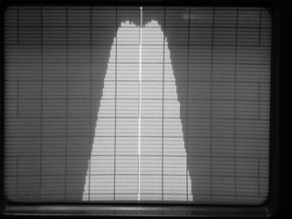
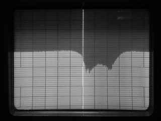
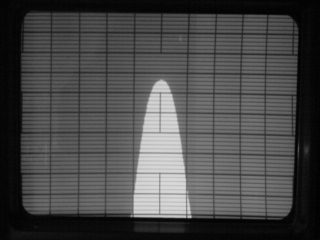
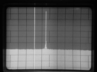
If you really want to see what the IF passband looks like you must use a spectrum analyzer with tracking generator. Below are two random examples of filters tested in a fixture with impedance matching transformers and correct filter termination resistors. A ripple of 3dB or less is considered acceptable (the less ripple, the better). The horizontal scale is 500Hz/Div, the vertical scale is 1dB/Div, and the bright line is the cursor set at 3395.00KHz):
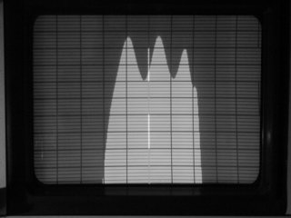
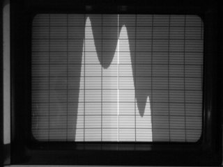
Heathkit 404-283 SSB Filter 2.3Khz at -6dB, CF 3394.89Khz, 8dB ripple
If the filter has shifted and/or the crystal frequencies need to move "a little", Mark WB8JBR has found that 100pf added in series with the crystal will move it up 100Hz or adding 10pf in parallel will move it down 100Hz. You can adjust your crystals accordingly or get others if they are far off. Even moving the whole IF Passband 1 KHz will not affect operation as long as everything moves TOGETHER and the proper relationship between filter center frequency and side slopes is maintained. Trying to repair a filter is difficult and requires a large soldering iron. Best to look for another filter if it's really bad.
For those of you who find that the "E" board has all the CW filter components but no CW filter (so it had one installed at one time), all I can say is that I share your feelings. They are not cheap to replace.
For those of you who want to install a CW filter but find none of the components installed, you can add the components per the schematics (your SB-104(A) schematic or the one referenced earlier in this repair section). The component values are readily available or can be made up.
CARRIER OUT (pin 19) should be .1VRF for all modes (USB/LSB/CW).
Several of these boards have had "low audio" for various reasons. Heathkit implemented a "talkback fix" which substantially reduced the gain of the audio preamplifier by changing R578 from 330 ohms to 1.8K ohms and R581 from 100K to 1.8Meg ohms. Optimum values for your unit might lie somewhere in between.
On one "F" board, after checking everything to find the cause of "low audio" the IF FET (Q501) was suspect. After removing the FET, a small piece of the shorting wire was found, still in place. This wire is installed during shipping/ handling to prevent electrostatic discharge from harming the FET and Heathkit clearly states to remove it after installation. Sometimes it's not removed and sometimes it breaks as it's being removed, leaving part of the wire behind. You can't see the piece of wire unless you pull the FET and examine it closely.
If some audio signals are distorted and strong signals seem to readily overload the receiver, check the AGC by turning it "off". If the audio is equally poor with the AGC "off" or "on", there is probably a problem with the AGC circuitry.
This is along the lines of "better performance" but the fix to replace the 4.7v Zener (ZD502) with a lower voltage Zener (around 1.5-2v) is a good idea. Or you can replace the Zener with two (in series) silicon signal diodes like two 1N914's in the reverse polarity. Any reduction from the original 4.7v Zener will greatly improve S-meter performance for low level signals. The S-meter potentiometer will have to be readjusted.
Speaking of the S-meter potentiometer, these tend "open up" at the ends over time, so check yours carefully if you have intermittent S-meter activity and replace the potentiometer if required.
You might also replace some of the coupling capacitors in the audio section
with Mylar capacitors to improve audio quality (C548, C549, etc).
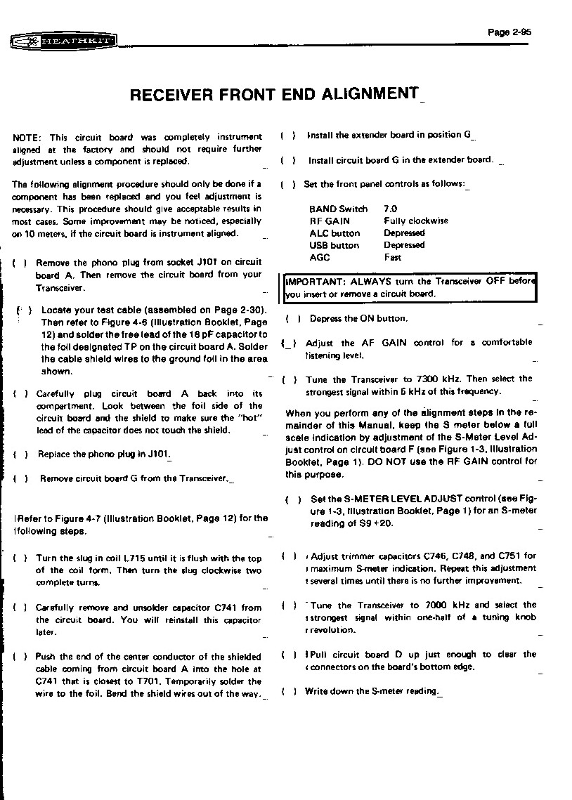
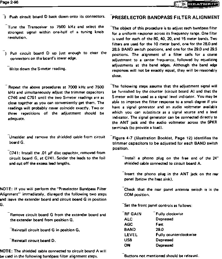
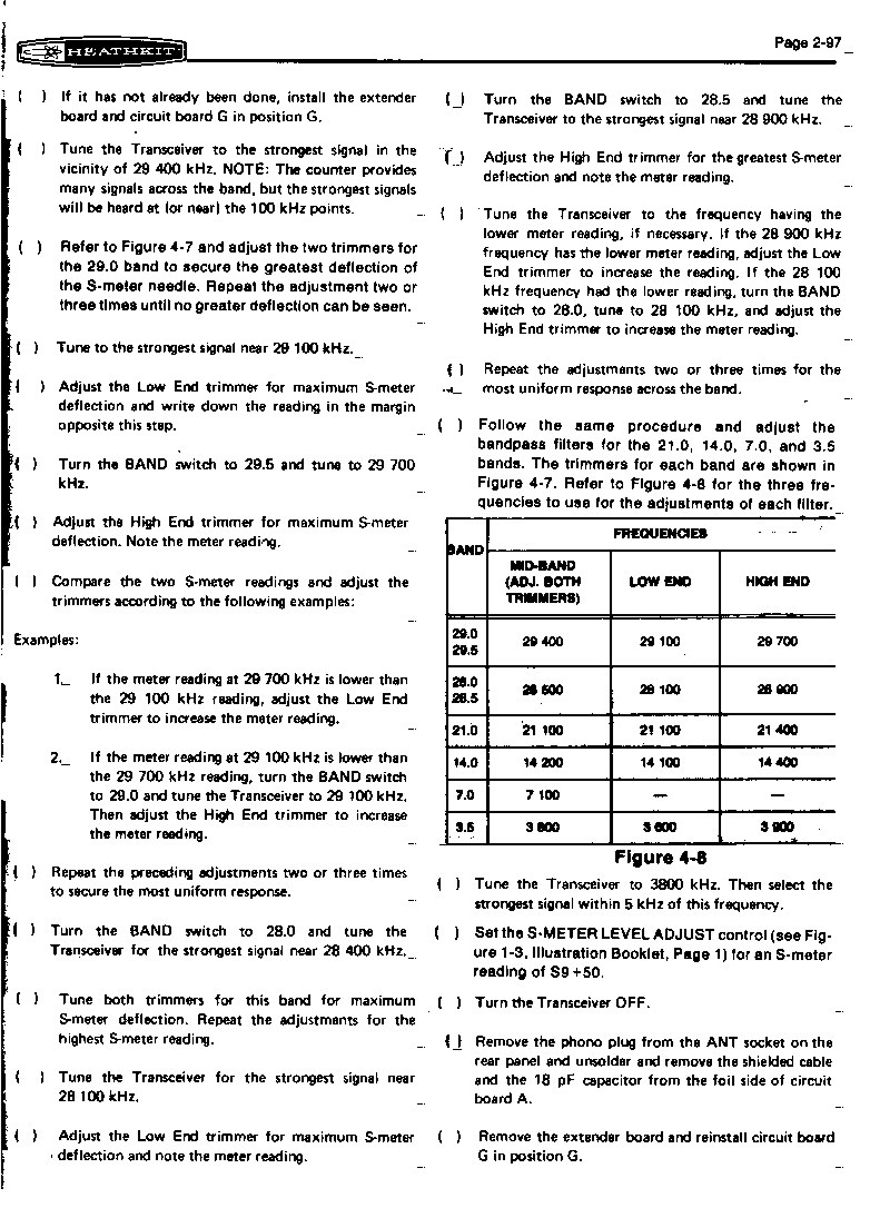
This is one of the most difficult boards. The alignment instructions were often not followed correctly and it has been stated that the initial "G" boards (#85-1459-1, #86-1666-1, #85-1708-2) used in the HW-104 and SB-104 lacked sensitivity (some of this is true, some of it may be due to the alignment that is critical). Later "G" boards (#85-1931-1) were supplied fully assembled and aligned by Heathkit. The later board uses a single 2N5109 broadband RF amplifier (Q702). The earlier G" boards use multiple FETs and FET mixers. For comparison purposes some measurements were made between the two types of "G" boards on 20m and with everything else equal, there was an 8dB (S/N)/(N) ratio improvement with the later board in my test. By the way, don't confuse "Sensitivity" with Minimum Discernable Signal ("MDS"). Many signal generators require an external 50 ohm termination for the attenuator to be accurate. Without it, you may actually have 2x-3x more voltage coming from the signal generator than shown on the meter.
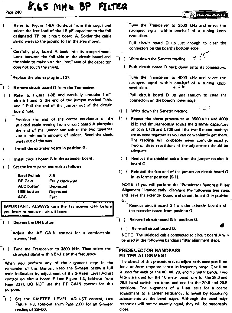
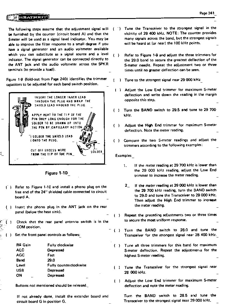
Alignment proceedure for the SB-104:
SB-104 page 1
SB-104 page 2
SB-104 page 3
SB-104 page 4
SB-104A page 1
SB-104A page 2
SB-104A page 3
SB-104A page 4
The SB-104A Tech Schematic file is located at SB-104A Schematic.
The best way to tune up a "G" board is sweep alignment. A scope and signal generator are good, a sweep generator and scope are better, and a Spectrum Analyzer with Tracking Generator is best. SAs with TGs are available on e-Bay for $400 to $700. If you are using a signal generator and a scope, check at several frequencies Hi/Mid/Lo and optimize for the best overall readings. This is especially important for the 8395KHz-8895KHz filters.
There is another difference between "G" boards. The earlier HW-104/SB104 boards (with several FETs) have an RF gain input on pin 5 and the later "G" boards (one RF transistor) have this point grounded. Not a problem as long as you have a series resistor to +11V on the second RF gain control to limit current. Much better to remove the lead when using a SB-104A "G" board in an older HW-104 or SB-104.
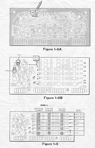
The alignment of the trimmers on the board is not optimum if the trimmers are peaked at max or min capacitance (white "depressed" dot next to the black "raised" dot is max capacitance). Component values change over time and sometimes changing the fixed mica capacitor values is required for proper alignment. The toroid inductance can be changed slightly by spreading the turns apart more....reduced inductance, or by moving the turns closer together .....increased inductance. I've adjusted a few with good results and it's easier than finding/soldering another fixed capacitor.
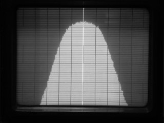
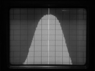
Now how do the "G" board bandpass filters for the various bands compare ? Three SB-104A "G" boards were checked. Board 1 was originally tuned up by Heath and was "untouched", board 2 was also tuned by Heath but has since been retuned, and board 3 was modified with Mini-Circuits mixers and has been retuned several times. The shape (rolloff) of the passbands are roughly equal between boards as is insertion loss. However, the 10m Lo and 10m Hi passbands on board 1 peaked 9dB less than the other boards. The Heath toroids used are 15.5uH (white dot), 7.0uH (no dot), and 4.5uH (red dot). The board 1, 10m Hi bandpass filter couldn't be tuned above approx 24Mhz and the toroids measured 5.5uH-5.8uH. These toroids also have 16 turns vs 14 turns on other 4.5uH (red dot) toroids. After removing 2 turns, it brought the inductance down to 4.3uH, and now it tunes 10m Hi. The core material may have changed over time on these particular toroids ?? Most bandpass filters were "right on" but some bandpass filters were found to be off in frequency by up to 2 Mhz and could be easily retuned (components change value over time). All the capacitors tested within specs. Since all the boards, after adjustment, were roughly the same (except for the 10m Lo and 10m Hi mentioned above) here are examples (below) of the various bandpass filters for 80m on the left and 40m on the right (vertical scale is 1dB/div, horizontal scale is 200Khz/div, bright vertical line is at the center of the entire ham band).
Here are some examples (below) of bandpass filters for 20m on the left and 10m on the right (vertical scale is 1dB/div, horizontal scale is 500Khz/div, bright vertical line is at the center of the entire ham band).
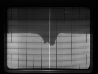
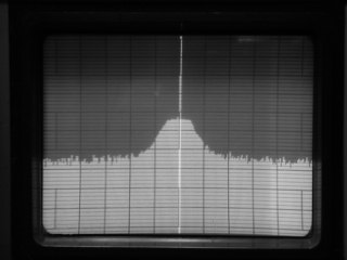
The 8395-8895KHz trap (L715) does tune OK but the best trap characteristics (3 boards) are obtained at roughly max inductor setting (slug nearly all the way into the coil). The inductor covers a range of roughly 0.16uH to 0.26uH and filter analysis shows 0.26-0.27uH is required.....that's also what the spectrum analyzer shows. With the slug 7/32" into the coil, the trap gives -3dB at 7.98-9.19MHz and -20dB at 8.42-8.88MHz. With the slug 1/16" into the coil the trap affect is less than -10dB and it's at the wrong frequency.
As an example (below) here are two S.A. traces. The one on the left is 7/32" into the coil (0.26uH) and the one on the right is 1/16" into the coil (vertical scale is 10dB/div, horizontal scale is 500KHz/div, bright vertical line is at roughly the center frequency of 8645KHz).
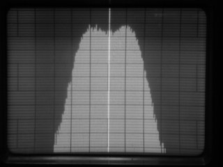
The 8395-8895KHz bandpass filter (L717, L718, L719) is really critical to tune up by ear with a signal generator. I tried several times and got "close" only. With the spectrum analyzer a really nice flat topped passband with the following characteristics can be had.... -3dB at 8.37-8.95MHz and -30dB at 7.74-9.61MHz. Looks really nice and identical to the one Heath factory tuned board (vertical scale is 1dB/div, horizontal scale is 200KHz/div, bright vertical line is roughly at the center frequency of 8645KHz).
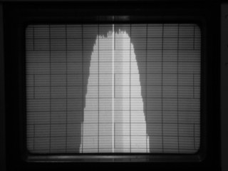
As an example (below) of how critical the adjustment is because the bandwidth is so narrow, the trace on the left is tuned up via the S.A. and the one on the right has the three trimmers less than 1/16 of a turn turn off optimum (vertical scale is 10dB/div, horizontal scale is 500KHz/div, bright vertical line is at roughly the center frequency of 8645KHz). The trace on the left is the one above but the scales are different (10dB/500KHz vs 1dB/200KHz).
IMPORTANT: Critical items on the later "G" boards and other boards are the discrete component Double Balanced Mixers (DBMs) and their FH-1100 Hot Carrier Mixer Diodes. If these diodes need to be replaced, they should be replaced as a matched set. An acceptable substitute is the HP 5802-2805 Matched Quad Mixer Diodes available from sources such as Brad Thopmson ([email protected]). Proper operation of the discrete component Double Balanced Mixers (DBMs) on the various boards is critical for reducing undesirable mixer products ("birdies" in receive or unwanted "spurious signals" in transmit). Substituting DBM assemblies from Mini-Circuits (SBL-1, for example) has been mentioned in several articles and might be a better alternative to the discrete components because they are fully shielded, well matched, small, but do require some creative mounting techniques. This is not to say that they are "electrically better". I've found the Heathkit DBM design (vs the SBL-1) to be excellent with the matched HP mixer diodes. Do not substitute any silicon signal diode such as a 1N914 "because they were handy", the resultant loss of low level signal sensitivity is dramatic due to the higher bias levels required, etc.
Another item, which will show improvement, is to properly match the DBM input and output impedance (usually 50 ohms). The inputs are not nearly as sensitive to this as the IF output, so focus on that end of the DBM to reduce unwanted reflections and add a "diplexer" to the IF output. A diplexer is nothing more than a bandstop filter (the IF frequency range) to ground through a 50 ohm resistor and a bandpass filter to the next stage terminated in 50 ohms. With this, the DBM has proper 50 ohm termination of frequencies inside -AND- outside the IF frequency range. Some designs have used a 3x desired frequency highpass filter through a 50 ohm resistor to ground and called that a diplexer.
The band switching diodes only need to be capable of switching at the desired frequency and if you want to reduce capacitive coupling, substitute PIN diodes or the HP mixer diodes which measure less than 2pf. The original Heath diodes measure 4-5pf. You know, seems like something basically wrong with diode switching of uV signals and a much better solution would be to use small (DIP size or smaller) relays to switch bands since you don't have "short lead" access to a bandswitch. The bandswitch would select the relays. Just to show one of the effects of using relays, here are two plots ....the difference is 2dB. This is the same 20m RF input filter (not yet tuned for optimum 20m coverage). Isolation from the (noisy) +11V supply, used for diode switching, should also help reduce "birdies" and should be the most desireable result of using relays ...haven't made that measurement yet. Scale is 1dB/Div, 1MHz/Div, and the referenced Datum at the top is the same.

The sensitivity of the later "G" board can be further improved by
replacing the 2N5109 (Q702) 1K collector resistor with a 1mH RF choke, the
560 ohm emitter resistor with a 100 ohm resistor, and the .005mfd emitter
capacitor with a .01mfd disk capacitor .......per the N2EO article.
| dBm | power | microvolts (rms) |
| -134.9 | 3.2E-17 | 0.040 |
| -133.0 | 5.0E-17 | 0.050 |
| -131.4 | 7.2E-17 | 0.060 |
| -130.1 | 9.8E-17 | 0.070 |
| -128.9 | 1.3E-16 | 0.080 |
| -127.9 | 1.6E-16 | 0.090 |
| -126.2 | 2.4E-16 | 0.110 |
| -125.4 | 2.9E-16 | 0.120 |
| -124.1 | 3.9E-16 | 0.140 |
| -122.9 | 5.1E-16 | 0.160 |
| -121.9 | 6.5E-16 | 0.180 |
| -121.0 | 8.0E-16 | 0.200 |
| -120.1 | 9.7E-16 | 0.220 |
| -119.0 | 1.3E-15 | 0.250 |
| -118.0 | 1.6E-15 | 0.280 |
| -116.9 | 2.0E-15 | 0.320 |
| -115.9 | 2.6E-15 | 0.360 |
| -114.9 | 3.2E-15 | 0.400 |
| -114.1 | 3.9E-15 | 0.440 |
| -113.0 | 5.0E-15 | 0.500 |
| -112.0 | 6.3E-15 | 0.560 |
| -111.0 | 7.9E-15 | 0.630 |
| -110.0 | 1.0E-14 | 0.710 |
| -109.0 | 1.2E-14 | 0.790 |
| -108.0 | 1.6E-14 | 0.890 |
| -107.0 | 2.0E-14 | 1.000 |
The SB-104-1 Noise Blanker is very effective on ignition noise if you are going to use your SB-104(A) in a mobile location. I have heard that it performs well on some power line arcing "spike" noise. This Noise Blanker has been adapted to several other units and there are conversion articles on how to install them in Collins KWM-2s, etc so there are those who regard the capabilities as excellent. For "normal" reception, I have not found the noise blanker to very useful but you should form your own opinion.
Since turning the NB "off" does not remove it from the circuit, you should bypass the Noise Blanker (jumper pin 1 to pin 5 on the NB connector) while chasing a receive problem. An excellent idea is to add a small (DIP) DPDT 12V relay at the NB connector to bypass the NB in the "off" position. The NB "on/off" would also pick the relay. It's been suggested to add some small coax from the NB socket to the NB switch for bypassing the NB, but I would go with the relay.
I've seen a SB-104 where the seller removed the Noise Blanker but left all
the wiring (making receive inoperative without the jumper) and a unit with a
NB *AND* a jumper installed under the chassis.
This is one of the high dollar boards in the transceiver. Often, low output is assumed to imply defective power transistors, but the problem can actually be elsewhere ....and much less expensive to fix. Example: low drive levels, low DC power, defective solder joints, wrong component installed, cracked foil leads on the transistors, intermittent coax connections, bad ALC level, etc.
The PA Board Check outlined in the Operations Manual is a good, quick check of PA board quality but it won't tell you which transistor is bad and even if it tests "OK", you may still have a PA board problem. On the other hand, If it tests "Defective", you definitely have a PA board problem. Measure from both foil areas (bases of the transistor pair) to ground on the small circuit card around L952 and L953 (nearest to the PA board connector) and it should read "0v" in Rx and around "0.65v" in Tx. Another excellent check of the PA card is to temporarily disable the ALC and see what the output is into a properly matched dummy load. You will see around 175 Watts on 80m with a correctly working system. Don't do this for more than a few seconds. The ALC, when working properly, should limit output to approx 100W.
Assuming you still don't have good output and have measured the DC Voltage at the PA, temporarily disabled the ALC, measured the input to the PA board (should be approx 8-9 VRF with the mic control advanced to fully clockwise (max power)) .....there might be a problem with the PA transistors.
Remove the PA board and check for hairline cracks in the RF transistor foil leads due to mechanical stress, check for bad soldering, check all the other components visually for correct values and soldering (...if it's never worked, there could be assy and component errors). After isolating them, test each individual transistor with a cheap (2,000 ohms per volt) VOM, Base to Emitter forward and reverse, Collector to Emitter forward and reverse. A low reading in both directions indicates the transistor is bad ("short"). No reading in either direction indicates the transistor is bad ("open"). Some variation in readings is perfectly OK. To isolate the individual transistors, cut the board traces (scrape the solder mask and resolder later) ....much easier than desoldering the transistor. This also allows you to compare readings between the four transistors. If you find a bad one (usually go out in pairs) you have the choice of replacing only the defective ones or all four. I've replaced only two with good results. Heathkit suggests that you replace all four as a matched set. This is not necessary if you can find transistors with BETAs reasonably matched. You will need a Transistor Tester to determine BETA, you can't really use a meter for a quick match based on resistance readings.
There are other RF transistors (available and less expensive today) which can be substituted (Motorola MRF455A, etc) but they may require some mechanical modifications. Use new heatsink compound when mounting the RF board to it's heatsink. Heatsink compound is available from many electronics supply places including Radio Shack.
The power transistors can be put under excess mechanical stress if the stud flanges (the surface which contacts the heatsink plate) are not all in the same plane. In other words if one transistor is tipped or mounted lower to the board, there will be mechanical stress when the nuts are tightened. The nuts only need to be tightened to insure good heatsink contact and holding the stud while tightening is important to remove torque from the foil leads.
The later level boards have 360pf mica caps from the collector to ground on all four PA transistors to stabilize 10m. If your "H" board does not have this fix, it's easy to install by tacking four micas onto the traces under the heatsink plate. Use micas that allow some clearance between them and the plate.
Check the shields on the coax connectors to the boards to make sure they are tight and "pinch" the four sides a little if they are loose ....causes all kinds of strange transmission problems and spurious output.
Max voltages (Mic/CW level control set for 100W output) of the PA Board
are on the order of 100VRF.
The problem with one "no output" SB-104A was that RFC902 was open. The break was where the coil wire attaches to lead and a little extra solder at that point fixed the problem.
Check the shields on the coax connectors to the boards to make sure they are tight and "pinch" the four sides a little if they are loose ....causes all kinds of strange transmission problems and spurious output.
The Low Power (at Mic/CW level set FCW) Output from the Driver Board
(NOT the PA Amplifier) should be about 9.5VRF for all bands.
If you are using a scope to look at signals, you will be amazed just how well this board cleans up the output signals if working properly. The SB-104A version of this board has a few value changes and adds L815 for 15m.
Make sure the ferrite beads are installed on the ALC line and are not broken.
Both the OSC Card and the Buffer Card are located in the VFO enclosure. To remove the VFO, pull the tuning knob, remove the outside vernier drive, remove the 4 screws holding the VFO to the chassis and pull it out from the top. You will notice the effort to keep components from physically moving inside the enclosure ....disk caps bonded together, OSC and Buffer card bonded together, very good mechanical connections, short leads, etc. However, there are some problem areas: Mike Bryce noted that when the bonding between the OSC and Buffer cards separated, it could cause VFO drift. It's also necessary to carefully route the wires to the variable capacitor away from the rotor plates to prevent unwanted capacitance coupling/changes. In fact, it would be better to replace those wires with a much heavier gauge to further prevent movement. On one VFO, a problem was encountered resulting in an intermittent loss of drive if you moved the 4-pin connector to the VFO slightly. This was traced to the ground wire from the 4-pin plug electrically contacting RFC-1201 inside the VFO. The wire needs to be routed away from the RFC.
Voltage at the Drain of Q1202 should be around 2.5VRF, Source of Q1202 should be around 1.7VRF. Output from the VFO (gray wire) should be .18VRF.
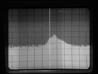
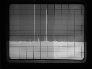
If the VFO output is set too low, the balanced mixers don't receive enough drive and the display is unstable (the HW-104 didn't have a display problem, of course). If the output is set too high, there are unwanted "birdies" on receive and "spurious signals" on transmit. As an example, the trace (below) on the left is the VFO output optimized. The one on the right is what happens with it set too ....LOW. Spurs were generated when the VFO was set too high which was expected, but similar spurs were seen when it was set too LOW (vertical scale is 10dB/div, horizontal scale is 100KHz/div, narrow filter, bright full vertical line is the Spectrum Analyzer cursor).
Both the OSC Card and the Buffer Card are located in the VFO enclosure. See
above.
This is a small board located under the chassis. The SB-104 version (#85-1633-2) has 2 inductors and 8 leads to it. The better SB-104A version (#85-1930-1) has 3 inductors and 4 leads to it. If your unit was serviced by Heath, you probably have the SB-104A version. The earlier board had some problems .....if the VFO was set too low the display was unstable and if too high, there were unwanted "birdies" on receive and "spurious signals" on transmit. The HW-104 didn't have the above display problem, of course.
Voltage into the VFO Filter Board for a SB-104A (pin A) should be .18VRF
and output (pin D) should be .05VRF.

Last updated.... when I got "a round tuit" 01/08/02