Bringing another R-390A back to life
Bringing another R-390A back to life
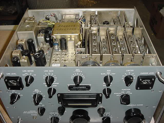
R-390A purchased at a local swapmeet. Always wanted one because of the performance reputation and the amazing mechanicals. Any receiver which utilizes 26 tubes and, for tuning, requires 14 cams and 30+ gears to operate 8 slug racks racks and a PTO, has got to be an interesting receiver. Serial #26xx manufactured by EAC (a division of Hammarlund) per 1967 contract.
All the component serial numbers are roughly the same as the unit serial number when you consider yield off a typical electronic sub assembly manufacturing process. All the components, except the Cosmos VFO, are manufactured by EAC.
The individual selling it said: "he was absolutely NOT going to take it back home", "it had very low audio", "it didn't work right .... might be a bad tube" (....sure it is), and had two loose cables (repair effort ?). I detected a level of frustration and he was quite happy to part with it.
Replugged the loose cables and powered it up on a variac, nothing unusual,
glad to see good B+ (power transformer is OK). Dug around
in the junkbox for a 600 ohm to 8 ohm transformer and actually found one.
Sure enough, very low audio with both the RF and AF gain fully advanced.
Tested all the tubes (all good), borrowed a manual, and later downloaded the
excellent Y2K R2 version. Found the two jumpers on the back for remote AGC
and RF Gain missing. After making some from aluminum scrap, there was plenty
of audio noise, but still ....no signals.

Jumpers made from scrap aluminum
The mechanicals are impressive but several of the slug racks would cam up and stick. Greased all the bearing points with a little white grease and still had two which sometimes stuck. Removed the two slug racks and cleaned the slugs and the inside of the coil forms of all residue. They all now follow the cams.
On the advice of several R-390A experts, pulled the electrolytics and rebuilt them with new internal parts before they went bad (been there, done that, didn't like it). Found some square aluminum cans with octal plugs to use.

New electrolytics
Measured the 2nd oscillator and TP E-402 is low, but when connecting the scope ground, tripped the GFI. Found the chassis to be slightly AC "warm" and was informed by several people that R-390As trip the
sensitive GFIs we have today. Replaced the AC filter with a 3A junkbox
unit which has an IEC 320/13 connector. Made an aluminum adapter plate (no
extra holes, reversable). Had to relocate the bathtub capacitor a few inches
to make room, also no new holes.

Modern AC Filter added using an
aluminum adapter plate
Shaved a little plastic off the mating AC cord plug to allow full insertion. Works great, no more tripped GFI, no more AC "warm" chassis.
The 2nd oscillator levels are -2.5V to -8V at the TP and will require further investigation but you should hear "something". Tried all the bands and frequencies. Looks like the 1-2Mhz band "works so-so" but nothing else. You can barely hear the calibration signal with RF and AF gains advanced on the other bands.
Time to take the unit apart because I want to add all the proactive changes and improvements anyway. For a complex receiver, it was
easy to disassemble the modularized unit .....even the RF deck.
Most difficult task is to get the Bristol wrenches to bite (almost an
interference fit). Made a "long" Bristol from a section of fiber rod,
drilled a hole in it for the small end of the Bristol, and attached it
with two small cable ties ...works well.

Tools made to service the R-390A
7-pin extender, long Bristol, tube puller, short phillips
Start checking the various sub assemblies for bad capacitors, changed resistor values, etc .... can't find any values outside 10-15%.
Proactive circuit changes:

Connector to use the balanced input
(better input sensitivity)
Experimented around with the 2nd oscillator, changing values, better 6AK5, power it up on the bench and am not able to get -4V to -11V levels at the E-402 Test Point (six bands are above -4V). Maybe it's sluggish crystals. Four of the crystals have one pin which is very loose. Pulled the four sockets and replaced the pins (one came out in two pieces the others had no spring action). Noticed that the registration of the number tape, at the front of the deck, is "off" by a little more than 1/16" to the left. Since the 32 switch contacts are very closely spaced, I put an alignment mark on edge of the hole to allow proper alignment in the future. Noted the min/max capacitance position of the trimmers since you don't want that to be the peak. All have two peaks ...OK.
Checked all the cables by wiggling them while measuring continuity and found one intermittent ....P-218 (one of the loose cables when I got the unit). Turns out the center pin is not soldered to the wire. Easy to fix but the radio is not intermittent, it's dead.
While examining the RF deck a gear fell out. Took a while to find out where it goes. Guess what ? ....it's off the RF bandswitch shaft which is "fixed" in the 1-2Mhz position. The gear clamp is busted and a new one ordered from Fair Radio. Ordered one of their reproduction top and bottom cover sets too (very thin aluminum).
Time to decide which mica caps are to be replaced because many of them "fail" at 500V in the "mica" cap position on the Heathkit IT-28 capacitor checker. On my IT-28, the eye closes at roughly 0.1uA for the "paper/mica" cap position which is a little on the sensitive side (an Eico capacitor checker I had, closed at 1.5uA). So here is a better way: after determining that the voltage settings on the cap checker are "close", insert a digital uA meter in series with the leads and read the real leakage at the specified WV. The C327 mica (Chuck Rippel says it's a problem capacitor) read 2.5uA ....clearly a bad mica. I replaced it with another mica because it's part of a tuned circuit and disk ceramics move around too much. Most of the mica capacitors which closed or started to close the eye on the IT-28, read less than 0.1uA at 500V ...perfectly good. One more bad mica (also used at B+ levels) was C286 which measured 4.0uA leakage. That one will hose up the bias levels at the 2nd mixer.
Received the gear clamp and re-installed the gear on the bandswitch shaft (glad I'm not a neurosurgeon) . Now the bandswitch is operational. Checked cam alignment in the 7+000 position, looks "OK". A little light lubrication since you can access everything while it's apart, some contact cleaner, and put the unit back together.
Had to make a tool for installing the Osc deck "third screw" ...the old I-forgot-to-install-it-before-mounting-the-front-panel (see R-390A tools above). Powered it up ....Nothing !! Not even the Broadcast band. Found that the Osc deck tube was not lit. Power at the Osc deck plug is OK, turns out the RF choke in the tube filament lead opened up (I probably did that). Fixed it and tried again ....Works !! Tuning was very stiff ...found the dial lock was not installed into the front panel detent, thereby putting excess pressure on the back of the disk.
A spot check of alignment looks good, so we'll use it a while and get familiar with what else needs looking into. The tuning is still too stiff and I think the source is the VFO. The S-Meter acts "very damped" and the AGC does not respond as it should for the three positions.
Got tired of the 1-2 second signal blanking and carrier meter kick when you switch from "Low" to "Med" AGC (a well known R-390A problem). Installed a 1W 10V zener with a 470 ohm resistor in series from the AGC terminal screw to a ground screw on the back of the unit (will install inside the IF deck later). Minimal kick and minimal blanking and no ill effects observed. Lot better than the over -100V spike when you dump the 2mfd capacitor. If you have the Dallas Lankford 2 diode SSB enhancement, you must install back to back zeners or a 10V MOV (18V DC clip level) or you will take out the one SSB diode when switching between "Med" and "Low" AGC as the capacitor charges and you develop a positive spike across the 470 ohm resistor.
Still have a problem with the carrier meter repeatability, crank the RF gain down and back up and you get a completely different reading. Zeroing the meter varies also ...it's OK for a while, then it's off again. Turns out that the meter is "sticky" .....put another uA meter in parallel and if you slowly turn the adjustment potentiometer up until the other meter reads "x", the carrier meter reads "20". If you turn the pot to full scale and slowly turn the pot down until the other meter reads "x" again, the carrier meter reads "60", sometimes "40". Took the meter apart (fun job) ....that ring with the 4 indentations is NOT threaded into the housing, its just a "pressed in" soft metal ring. I drilled through one of the indentations and pried the ring out. Will use silicone adhesive to re-install the 4 sections. Also you can now clean the glass ...I don't know how a sealed meter gets junk on the inside of the glass, but it does.
The carrier meter "zero adjust" was basically non functional because the movement did not move freely. Loosened one of the movement end screws a 1/4 turn and the meter now moves freely and the "zero adjust" works. You can remove and reinstall the meter with the front panel in place. Removal is straightforward and the nuts and washers fall out the bottom, reinstallation requires taping the bottom two nuts to something, start the screws, pull the tape loose, and tighten all the screws.
Meter works great, no more "sticky" carrier meter, and that's mandatory for tune up of the R-390A.
The Carrier Meter adjustment is sensitive to adjust and I assume that's why some people suggest that it be replaced with a 10 turn potentiometer ...or maybe it's burnt/worn because the majority of the current (around 16 ma) does not go through the 22 ohm, 1 watt resistor leg, it goes through the much lower potentiometer resistance. My carrier meter is adjusted properly when the pot is less than 10 ohms ...not much on a 100 ohm pot range.
If you look at the schematic, the 22 ohm resistor and 100 ohm pot are part of the cathode resistance circuit for the 4th IF and I believe the 100 ohm pot was intended as a voltage divider for the meter. The way it's shown in the schematic will affect the cathode resistance some as you vary the "adjusted pot" value ....and it makes adjustment very sensitive.
If you move the green/blue wire to the center tap and remove the wire short from the center tap to one end, you have essentially made the pot a voltage divider for the meter and the cathode resistance stays fixed at about 19 ohms (parallel 22 ohm and 100 ohm). Seems to work fine (local broadcast stations still go 2/3 scale or better), the Calibrator signal indicates 40db +/- and the potentiometer is much easier to adjust. I've been told there is some loss of meter sensitivity by doing the above but I haven't verified that. Some replaced the 22 ohm resistor with a 8.2 ohm resistor to keep the higher sensitivity level.
All the tune-up adjustments appear to require minor tweaking. The 455Khz IFs (T501, T502, and T503) are stagger tuned, not all peaked at 455Khz . The IF gain was WAY high (more is not better, generates noise). Readjusted the gain to reflect the correct -7VDC +/-1V on the "Diode Load" jumper for a 2uV signal from the signal generator.
One more problem found. Pin 6 of P-112 was intermittent which disrupted the AGC in the IF deck.
Nice receiver.