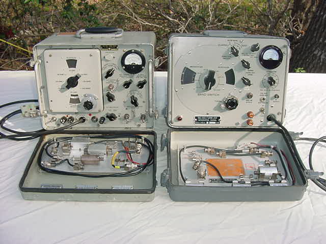
AN/URM-25D or -25F Signal Generator Repair Hints and Comments
These units are still excellent today, but after 50 years or so could stand
a little work and many which supposedly work correctly, don't. I'm told
Dallas Langford published an excellent "URM-25 Notes" article in the Hollow
State Newsletter which is mandatory reading for those wanting to really
restore their URM-25 signal generators.
Manuals for both the URM-25D and URM-25F (and a heck of a lot of other
stuff) are available from me on the HBR Receiver CD for $10 postpaid in the
US or $12 Worldwide.
If you have a non working unit, these are some things I look for (after
working on about 10 generators). The HBR Receiver Site has additioanl tube
equipment debug:
- Are the fuses OK and switches set correctly ? ....wish I had a $1 for
each time..... The "X-MULT" switch on the -25D must be set to the correct
band being used or the waveform will be distorted (easy to forget). The
"SET CARRIER" control (on the -25D) or the "RF OUTPUT" control (on the
-25F) should be set to indicate full scale on the meter with the
"Microvolts" control set to max (fully clockwise) ...then use the
"Microvolts" control to set the desired level. These setings will vary
substantially from band to band. Sometimes backing off on the "SET CARRIER"
control some and increasing the "Microvlts" setting, results in a
slightly cleaner waveform.
- Does the meter work in the 400/1000 Hz modulation position....if so,
the audio oscillator and modulation circuits are probably OK. Does the
meter read RF in the CW position....if so the RF section is probably OK.
Does the meter read RF output on all bands....if not, it's probably
a dirty intermittent contact on the wheel and requires cleaning/lubrication
(DeoxIT). Do the switches work smoothly....if not, they probably require
some cleaning/lubrication (DeoxIT). This also applies to tube socket pins
which can become intermittant due to oxides over the years.
- Take the front panel off (rock it back and forth so any protruding screws
clear the lip on the rear cover) and disconnect the two power plugs on
the -25D or the one power plug on the -25F.
I have found one unit which came "pre-unplugged".......wonder why it
didn't work ? This is also a good time to remove some of the inevitable
dents in the cover. Aluminum is very easy to "work". When reinstalling
the front panel, don't pinch the power cords between the panel and the
rear cover lip.
- If you have non-operation on some bands, the spring fingers are probably
not making good contact on those bands. Two -25F units required
moving the wheel with all the tuned circuits 1/16" inward to make good
spring finger contact.
- Check the tubes, there are 9 in a -25D and 8 in a -25F. Some are quite
difficult to remove but keep rocking/pulling them until the come loose.
There used to be a puller available for situations just that. If you have
one, lucky you. It's best to check the tubes on a Dynamic Mutual
Transconductance tester (TV-7, nearly all Hickoks, B&K 747, and many
others). When reinserting miniature tubes where you can't see well,
the little tab on the socket shield indicates the location of the pin gap
(between pin 1-7 or 1-9). On the -25F, remove the large capacitor (that's
what the wing nuts are for) so you can get to the last 3 tubes.
- Visually inspect the wiring. I have found -25D and -25F wires which were
never soldered (apparently passed QA when the wires still made contact),
broken solder joints (one which was held together with Scotch tape and
another which was apparently part of a repair process which was not
completed). The most likely points are those which require de-soldering
for sub-assembly removal (like at feed-thrus, etc....especially the one
feeding V102 on the -25D).
- The large "Mica looking" caps on the -25D are really moulded paper
capacitors and are notorious for leaking. Some units will already have
them ALL replaced (good move). These are the brown rectangular capacitors
on the -25D circuit board, the two closest to the attenuator are .2mfd,
the two at the other end are .1mfd, and the smaller ones are .01mfd.
Sometimes you can see them actually "oozing" some fluid (which it's
probably NOT good to ingest). Out of 17 of those caps tested, 16 leaked
....some indicated excessive leakage at 25V. Best to replace them all.
The number of times you will take your AN/URM-25D Signal Generator apart to
fix it, will be directly proportional to the number of these capacitors
left. On the other hand, I have yet to see one of the smaller value
Mica capacitors which was bad but the sample size is small.
- One of the -25F units would loose modulation after about 20 minutes.
Thought it was a bad mode switch because after disassembly and cleaning,
it worked again. Turns out it was a leaky cap affected by heat. Good idea
to replace all the tubular .01mfd, .05mfd, and .1mfd caps on the audio
board (they all showed some leakage) .....no more modulation problem. OK
to use disk caps since this isn't high fidelity and 600V tubulars are
hard to find.
- The cathode resistor bypass capacitor on the 6AG7, if leaky or open, will
dramatically alter the RF output.
- Check for B+ at any convenient point ***Careful and don't get across
exposed voltages** and filament voltage. I have not found any power
supply problems on the 7 units I've looked at. The electrolytics have
been found to be darn good and a little extra leakage in power supply
electrolytics does not hurt any function.
- A quick way to check for a leaky capacitor is to power the
unit up without the tubes installed (except for the voltage rectifier and
regulator). ***Careful and don't get across exposed voltages***. Measure
every tube socket grid pin (from either the top or bottom). It doesn't
take much current through a 1Meg or 100K grid resistor, due to a leaky
coupling capacitor to the previous stage, to bias the tube and cause
signal distortion. Measure
the tube plate voltage which should be the supply voltage (there is no
load with the tubes pulled). If you do see a drop you have a leaky bypass
capacitor in the plate circuit. The tube screen voltage should measure the
same on both sides of the screen dropping resistor. If you measure a voltage
drop you have a leaky screen bypass capacitor pulling current through the
screen resistor.
- The recommended debug sequence is just like on transmitters, from the
oscillator out. Check the signals at the grids/plates, when you note
a problem, it's probably the previous stage.
- There were several changes throughout production, so the schematic you
have might be slightly different from your unit.