Battery Powered Tube Regenerative Receiver
Battery Powered Tube Regenerative Receiver
This is my attempt to come up with an improved design point relative to the earlier Air Champ AC-100 and see what can really be done with a Regen.
My criteria was:
Basic Regen design is pretty common, so BEFORE the schematic comes the "concept stage", the "what's available in the junkbox stage", back to the "concept stage", followed by the "mechanical/electrical layout stage", then sketch a rough schematic ......and do it all over again.
The BC-221 has always impressed me as having about the simplest, smoothest, no backlash, tuning mechanism which is readily available to us. In fact, I picked up another two beat up BC-221 derivatives (forgot the numbers) at the last swapfest, one for $5 and one for $7 ....can't beat that for really good parts including the covers.
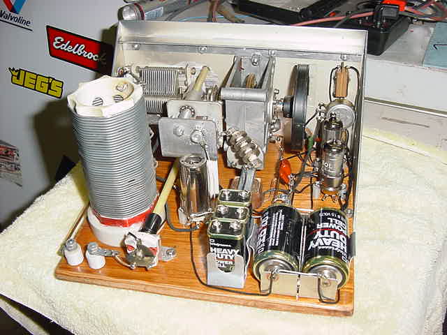
This is a Regen and all Regens should be breadboarded on a piece of plywood (personal opinion based on my first experience). An 8" x 9" breadboard looks about right and will fit inside the diagonally cut covers of and old BC-221 derivative (see the picture). The tuning mechanism and variable were mounted on the "front" panel and the panel was reinforced with extra ribs to reduce flexing. Having both the tuner mechanism and the variable capacitor on the same panel prevents additional movement. Selection of a good "solid" coupler and alignment of the 2 shafts is important. If you use shims, you still need solid mechanical mounting and aluminum is easy to work.
After measuring the coil with my invaluable AADE L/C Meter and doing a little figuring, the coil I had picked out should cover the desired frequency range with 4 taps and a smaller value tuning capacitor for the higher frequencies. Molex connectors were chosen for the taps because they are a good connection (better than a clip), cheap, and provide the shortest lead length. The coil was located to give the tuning capacitor plenty of room and to allow for installing a shield if necessary. The antenna and ground connections originate in the same area to maintain short lead lengths. In order to lower the tuning capacitance, a crystal socket was installed at the tuning capacitor. That socket accepts a crystal base with either a jumper or 100pf SM capacitor to lower the effective tuning capacitance from 256pf to 72pf. Unused crystal bases are stuck to a magnet on the audio output transformer in the middle of the board to prevent loss.
Started with 1.5V batteries and 27V worth of 9V batteries for B+. Initial tube selection: 1T4/1U4 RF/Regen, 1U5 1st Audio, 3Q4/3S4/3V4 AF output.
Presently it's a two tube regen, 1T4 for the regen stage followed by a 3V4 AF amplifier, 36V B+, and the following controlables:
After the intial placement, mechanical assembly stage, and some experimentation, there were a few conclusions:
Back of the "under construction" Regen Receiver

Back of the "final" Regen Receiver (note changes, front remains the same)
Guess I better do a readable schematic, can't read some of my scribbling. Looked into "Tubepad1" (thanks Gary, WD4NKA); easy to use with Microsoft Paint (which nearly everyone has), plus you can make your own schematic "things". Sure is different (and simple) relative to the tools we used professionally at the office, but this is fun. And "poof" a schematic to reference. There have already been several changes including going with a 3S4 for the audio output, deciding that generating a few volts grid bias without an additional battery lowered the B+ excessively .....and going to a 1U5. Back and forth at least 3 times (better on paper than with hardware). All designs were slightly different, added the ZL2JJ audio filter, changed a few values per the RCA tube manual, etc.

8/17/04 3 stage Schematic....guaranteed to change
As I optimize the receiver and tweak values more will be added. Time to stop writing, heat up the big Weller, and start melting solder .....and find another small audio output transformer.
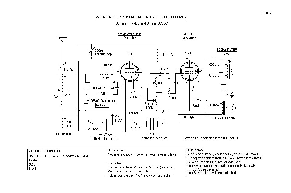
8/30/04 2 stage Schematic....this is the one I "settled" on
Jeff Noel, K4ZKU, decided to build the 3 tube version of the design and here is his report:
I built the 3 tube regen like you have on the web. It performs very well, better than the one I built when I was a kid (but that one won me a trip to Richmond Va for 4H). I even have a picture if it. The tube line up is 1L4 det, 1S5 audio, and 3A4 audio out. It is all built from junk box parts except the batteries. Here are 2 pictures of the brushed front panel and a top view.
Jeff
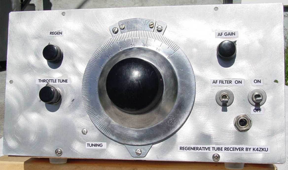
Front view of Jeff's Regen showing the brushed panel .......nice job, Jeff

Top view of Jeff's Regen