
Wall Wart Powered "Joneset" Transceiver........based on 1935 Frank Jones designs
OK, one more Regen.
My criteria was:
- Basic single tube (dual triode) Frank Jones "One Tuber" design point from 1935
for the receiver, but add an RF amp for isolation to prevent uneccessary radiation.
- A "natural" matching transmitter would be the 1935 Frank Jones single tube
push-pull dual triode transmitter
- Ham Band only focus via good bandspread tuning capability
- Smooth tuning, sufficient volume, and less critical regen adjustment
- Incorporate many of the design "Do's" from the regen experts
HOWEVER:
- Powered by a 12-24V wall wart
- Something different .....but for good reasons. Not a reproduction of someone
else's radio. "Interesting"
- Useful as a QRP rig. Stability and sensivity adequate for SSB and CW
reception on the ham bands
Basic Regen design is pretty common, so BEFORE the schematic
comes the "concept stage", the "what's available in the junkbox stage", back to the
"concept stage", followed by the "mechanical/electrical layout stage", then sketch a
rough schematic ......and do it all over again. Paper/Computer layout is cheap.
The BC-221 mechanism used in the previous Regen is not required here due to
the Band Set and Band Spread capacitor scheme.
I've also wanted to build a Paraset Transceiver since I was born in occupied Delft,
Netherlands and my father was part of the Dutch Resistance. I may yet build one, but
since making the decision to make this regen receiver a regen transceiver, this will be
my QRP "Paraset" and because it's based on Frank Jones designs, I'll call it the
"Joneset". More later..........schematic and layout under development, don't assume
this works yet.
It will be difficult to obtain power at these low
B+ levels, so I was looking for low voltage, high current tube possibilities like the 7044
dual triode. The other point is tube availability. Although I have several 7044s to use,
apparently they are not easy to find and an e-Bay search (which is probably
representative of availability and popularity) turned up the following numbers: 12AU7-93,
12AT7-88, 12BH7-12, 5687-11, 7044-1.
Might also look into the possibility of paralleling two or three for the Tx.
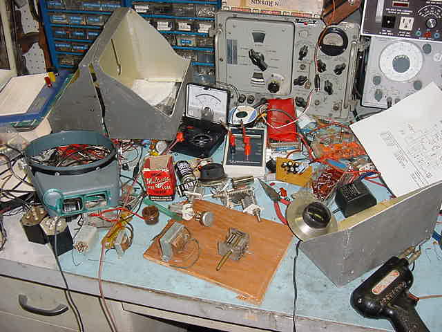
At the start of the project, a mess ? ......looks great to me, check out that dial
Decided to use the 9 pin miniature tubes which allows use of
MANY types of dual triodes (12AT7, 12AU7, 12AX7, 12AY7, 12AZ7, 12BH7,
6072, and with a slight pinout change, the 7044 and 5687). What I really need is a
"basic" triode for the Regen section and a "power triode" for the AF and Tx sections.
All the listed dual
triodes should work, but some have higher current capability at ~50V B+. The "best"
ones, on paper, appear to be the 7044, and 5687. The higher current capability at low
voltages is especially important if you want a 1-3 watts from the transmitter
For simplification we have the following controlables:
- RF Gain
- 15pf Band Spread variable for tuning (front panel)
- 150pf Band Set capacitor (front panel)
- 360pf throttle capacitor (front panel)
- Load/Tune/Spot for the Tx (front panel)
After the intial placement, mechanical assembly stage, and some experimentation,
there were a few conclusions:
- The throttle cap is not for decreasing tickler effectiveness by
bypassing the signal to ground, it's for feedback control to the grid. That's why MORE
throttle capacitance INCREASES the feedback.
- Focus not only on signal wiring for shortest path, good wiring practice, etc. but
also check/trace the ground paths. Especially important for a breadboard.
- After some experimentation, it was found that wall warts are really poor transformers
but I'm determined to use them. Voltage stability is a problem because of the Tx and a
design direction change has been made to make it a matching but separate Rx and Tx.
This opens up some additional choices for the Rx. One is 12VDC tubes which were
used in car radios of the late 50s. Some of the acceptable "power" candidates are the
12K5, 12U7, 12AE7, 12AL8
and several more. These tubes use space-charge principals where the cathode is
"well heated" to the tune of around 5-7W to make the electrons "boil off" the cathode,
a space-charge grid at B+ (which is the 1st grid) to attract them ....but since it's a
"grid" many pass through, the control grid which was the old screen grid, and the plate
to to attract and pick up the electrons. This method allows reasonable plate current
(and very high space-grid current) with 12VDC on the plates. The assumption with
a car radio is that voltages above 12VDC are a problem, current is not. There are also
some metalurgy changes and tube element physical changes. Interesting concept
and a candidate for a receiver using a 12VDC wall wart.
- Since the Regen and RF Amp portions do not require "power" like the AF section,
it was decided to use standard dual triodes which exibited good low voltage
characteristics. Some candidates: 12AT7, 7044, 7057, 12U7, 12BH7A, 5687, etc.
Many to pick from. Their use is as very low current voltage amplifiers.
- Because of the experimentation, which is really fun, it's usefull to build a
pluggable breadboard which allows tube base changes from 9A, to 9AJ, to 9H, etc.
I might keep this regen that way for future use as I find additional tubes to try.
- The Tx will require a larger wall wart, maybe starting with a 24VAC
unit and will use the Jones P-P CW Tx arrangement. The most viable low power
candidates
to date appear to be the 25C5 (in triode configuration), 25EH5 (in triode configuration),
5687, 7044, 12BH7A, etc. Some of these are also "high" filament power tubes (7W)
and I will try space-charge techniques to raise the plate current here too, even if the
tubes are not designed for it.

Back of the Wall Wart Powered "Joneset" Transceiver........sorta based on 1935 Frank Jones designs
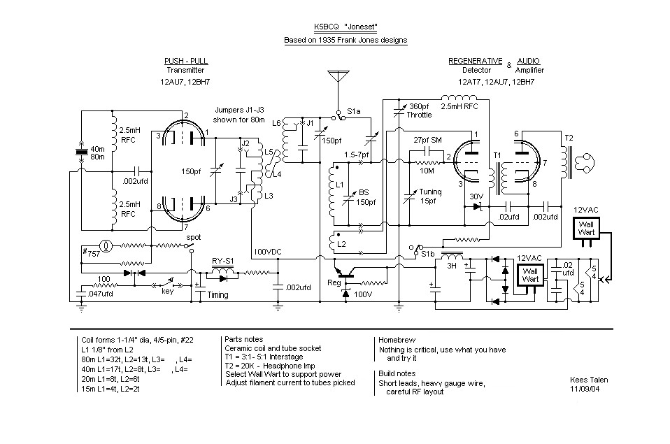
11/09/04 Schematic of the Wall Wart Powered "Joneset" Transceiver........sorta based on 1935 Frank Jones designs
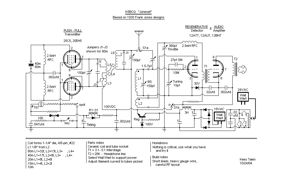
Or here is one with 25C5s in Push-Pull, many implementation alternatives for this basic "Joneset" Transceiver
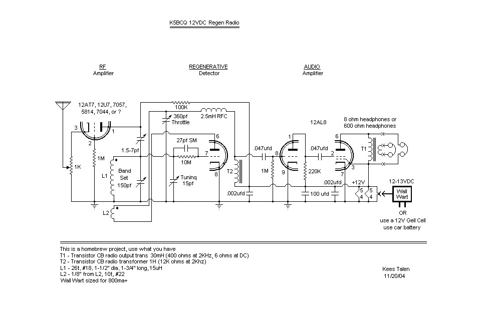
Where I'm headed today ........Rx portion of the "Joneset"