The purpose of this Web Site is to help you bring those Heathkit SB-101 and
SB-102 transceivers back to life. This information is also applicable to other
tube type units.
I'm told that Heathkit always reworked units returned for servicing to the
latest level, so if you have a unit serviced by Heathkit, the chances are
that the fixes have been implemented.
NOTE: These are "fixes" to make the transceivers function better. If your
unit does not receive, transmit, etc...there is a problem that needs to
be repaired ...first. Installing any "fixes" at this time would only
complicate matters.
Some may want to replace the "Ant" RCA phono plug with a round "bulkhead"
mount BNC connector. They fit nicely and provide an excellent, solid, 50 ohm
antenna connection. The RCA is also an excellent 50 ohm connector system
at 100 watts (better electrically than the old PL-259 UHF connector system)
but after many years the ceramic insert starts to chip and deteriorate
through use (compare it to the other RCA connectors). RCA connectors are not
real good for mechanical retention, especially where the cables are stressed
as they exit the unit. The BNC connector system is an excellent, low power,
50 ohm system ....both electrically AND mechanically (and convenient).
If you look at the airgaps, insulator thicknesses, insulator material, and
plating materials used, you will find them superior to the RCA connectors.
I've never had a problem with around 100 watts, although I would not use
them at 1KW. A BULKHEAD mount BNC connector does NOT modify the chassis.
Remove the RCA connector and install a bulkhead BNC, which has a small
threaded barrel on the back. The diameter of the threaded portion is actually
smaller than the RCA connector and it mounts in the hole with plenty of room
to spare.
Changing the mic connector from 2 pin to 4 pin is personal preference. Both
types of connectors are readily available today from various vendors, so
don't replace a 2 pin connector just because you can't find a 2-pin plug.
Asthetics: some of the knobs protrude too far, especially those with lever
type dual controls. There are two versions of the level type knob, one has a
set screw and the second has two tabs in the insert. The insert on the one
with the set screw is recessed placing it closer to the panel. The insert on
the one with the tabs is not pressed far enough. I've cut the back of the
insert down with a large drill bit ....works great. If the lever knob on the
filter selection requires too much force, lubricate the assy to prevent knob
breakage, they are difficult to locate/fix. Location of the other knobs can
be controlled through adjustment of the shaft bushing nuts on both sides of
the panel.
Don't start by powering the unit up as your first step. Something could
have been knocked loose due to shipping/transport. Also, since these are kits,
don't automatically assume they worked at one (or any) time. I can't stress
this last point enough because it's not usually part of commercial receiver
debug. I have found missing components, incorrectly installed components,
solder blobs shorting board traces, wires which were never soldered (and
are now corroded), and wrong value components installed. The point is, don't
automatically assume a complex kit is wired correctly even if you were told
"worked great the last time I used it" by the previous owner/seller.
Receiver Sensitivity
SB-102 receiver sections have fairly good sensitivity through the use
of low noise 6HS6 tubes. The same can be applied to SB-101 receiver sections.
More later with backup data.......
Chart showing dBm-power-microvolts for a 50 ohm receiver input
| dBm | power | microvolts (rms) |
| -134.9 | 3.2E-17 | 0.040 |
| -133.0 | 5.0E-17 | 0.050 |
| -131.4 | 7.2E-17 | 0.060 |
| -130.1 | 9.8E-17 | 0.070 |
| -128.9 | 1.3E-16 | 0.080 |
| -127.9 | 1.6E-16 | 0.090 |
| -126.2 | 2.4E-16 | 0.110 |
| -125.4 | 2.9E-16 | 0.120 |
| -124.1 | 3.9E-16 | 0.140 |
| -122.9 | 5.1E-16 | 0.160 |
| -121.9 | 6.5E-16 | 0.180 |
| -121.0 | 8.0E-16 | 0.200 |
| -120.1 | 9.7E-16 | 0.220 |
| -119.0 | 1.3E-15 | 0.250 |
| -118.0 | 1.6E-15 | 0.280 |
| -116.9 | 2.0E-15 | 0.320 |
| -115.9 | 2.6E-15 | 0.360 |
| -114.9 | 3.2E-15 | 0.400 |
| -114.1 | 3.9E-15 | 0.440 |
| -113.0 | 5.0E-15 | 0.500 |
| -112.0 | 6.3E-15 | 0.560 |
| -111.0 | 7.9E-15 | 0.630 |
| -110.0 | 1.0E-14 | 0.710 |
| -109.0 | 1.2E-14 | 0.790 |
| -108.0 | 1.6E-14 | 0.890 |
| -107.0 | 2.0E-14 | 1.000 |
IF Filter Passbands
One of the problems I encountered on a SB-104A, and it applies here also,
was that the IF filter passband shifted, reducing full output when using USB.
The Heathkit SSB filter BW on these SB-xxx units (as well as Collins KWM-2s)
is specified as 2.1KHz at 6dB down. Heathkit separates LSB and USB by 2.8KHz
which means USB and LSB are both 1.4KHz on either side of the filter center
frequency. For a 3395.0KHz filter that means 3396.4KHz for USB and 3393.6KHz
for LSB. Just for comparison, the Collins LSB/USB signals are separated by
2.7KHz, or 1.35KHZ on either side of their center frequency.
IF Passband problems can also occur if the LSB/USB crystal frequencies
move relative to the filter center frequency and side slopes. A quick check
is to switch back and forth between LSB and USB in a quiet section of the
band (no antenna). If you hear a difference in signal, they are not both
equally positioned on the opposite filter side slopes. A better approach is to
measure the oscillator frequencies with a frequency counter but you still need
to know what your IF filter center frequency is.
You can "see" the IF passband by injecting a 3395.0KHz +/-3KHz high
level CW signal from a signal generator and watching the S-meter. The high level
signal output is the separate output for a frequency counter, monitor, etc
....not the output that comes out of the attenuator. Pull the "Mode"
oscilator tube for this measurement. Very sloooowly tune the signal generator
through the IF passband and note the frequencies where you have a reading
of "S1". This will give you a rough idea of the passband but most signal
generators don't tune slowly enough, have bothersome backlash, and require a
calibrated frequency counter. If you detected several dips using the S-meter,
that's right, see filter profiles below.
If you really want to see what the IF passband looks like you must use a
spectrum analyzer with tracking generator. Below are two random examples of
filters tested in a fixture with impedance matching transformers and correct
filter termination resistors. A ripple of 3dB or less is considered acceptable
(the less ripple, the better). The horizontal scale is 500Hz/Div, the vertical
scale is 1dB/Div, and the bright line is the cursor set at 3395.00KHz):

Heathkit 404-283 SSB Filter 2.2Khz at -6dB, CF 3395.10KHz, 2.5dB ripple

Heathkit 404-283 SSB Filter 2.3Khz at -6dB, CF 3394.89Khz, 8dB ripple
If the filter has shifted and/or the crystal frequencies need to move "a little",
Mark WB8JBR has found that 100pf added in series with the crystal will move
it up 100Hz or adding 10pf in parallel will move it down 100Hz. You can adjust your
crystals accordingly or get others if they are far off. Even moving the whole
IF Passband 1 KHz will not affect operation as long as everything moves
TOGETHER and the proper relationship between filter center frequency and side
slopes is maintained.
Tuning Dial Plastic
One of the weaknesses of these units is the dial plastic. Over time, the
plastic develops stress cracks at the hub which go outward radially.
Small cracks are OK, but larger ones, especially if they crack the outer ring,
are annoying to use and cause slippage. I saw one dial which was apparently
heated and melted some around the edge (probably by having the pilot lamps
too close to the dial or using the wrong type of bulb ....requires #1815 bulb).
The other problem is "crazing" which looks like a spider web of small cracks
on portions of the dial.
The best solution is to buy a new manufacture replacement from Mike Shelton
(above). A second possibility is finding a good one off another unit or try
repair.
I have added epoxy to the cracks around the hub and on the front side
of the dial (thin adhesives which will flow into the cracks would also work).
Also add a little epoxy to the rear of the dial, being
careful to not get any in the spiral track, and add some to the four points
where the drive ring attaches. The idea is to strengthen the
plastic some and minimize continuation of the crack(s) ....seems to work.
Shrinkage of the drying epoxy MAY create additional stresses in the plastic
but time will tell. The cracks through the number portion
of the dial seem to be a combination of cracks which start at the hub and
align throught the 4 weakest/stressed points where the drive ring attaches.
This makes them prone to occur at "15", "40", "65", and "90" ....especially
"15". I took a good close look at "15" on a good dial and there seems to be a
tooling mark right on the "15", further weakening this point. The "crazing"
turns out to be cracking/wrinkling of the paint on the back of the dial. If
the paint could be removed and replaced or reflowed, the problem might be
resolved. I used Krylon flat black which has solvents which reflow the
existing paint, but thus far, results have not been satisfactory.
The pinch rollers slip if there is not enough friction between the
beryllium copper pinch roller and the tapered edge drive ring attached to the
plastic dial. There should only be enough force between the tapered drive ring
and the pinch rollers to prevent slipping. The pinch roller should
definitely not be visibly "spread apart", and absolutely not "pushed on all
the way". I believe the gap between the two disks (drive removed from the
SB-xxx) should be between zero and approx .002" to work properly. If the gap
between the disks is excessive, the spacer between them could be filed down to
bring the disks together (the shaft would also have to be filed the same
amount or a shim installed under the outer washer to allow tightening).
Slippage will also be present at some portions of the dial if the drive ring
is able to move perpendicular to the shaft and not stay centered. This occurs
if the four mounting tabs are improperly installed or if the plastic dial has split
(see above).
The main tuning knob pinch roller moves in a vertical slot and should be
adjusted per the manual. It's easy to "feel" when the pinch roller is engaged
correctly and with a slight downward pressure tighten the bushing nut. Use
only enough pressure to eliminate the slipping. Excessive pressure will make
the tuning stiff and will increase stress on the plastic dial.
If the "zero set" dial window (with the vertical line) is "floppy", the
clip holding it to the tuning dial hub has probably come off (the clip is
available at hardware stores). If the the
"zero set" dial slips, the pinch roller, made up of two spring washers, is
loose. It could be just wear over time but the problem I've seen here is
that someone pulled the front bezel/panel off, not knowing that the pinch
wheel is supposed to stay with the dial. As the aluminum shaft oxidizes and
increases in size, it tends to stick in the plastic bezel .....easy
mistake to make (personal experience). This stresses the rear spring disk and
bends it and/or pops it off the shaft. To fix, flatten the spring disk
if necessary. Place a nut on the shaft, against the front shoulder to
distribute the force, and insert the shaft loosely into a vice, small socket,
hole in a metal plate, etc. Put the rear spring disk on and make sure it's
flat against the shoulder on the rear of the shaft. Center punch the shaft
to expand it slightly and hold the rear spring washer. It would also be
prudent to find out where the old part(s) went if anything is missing.
If the pinch roller was just slipping due to age the fix is to add
some "grip" material like silicon to the inner surface of the pinch roller or
to the outer surface of the dial window. The dial window tracks in approx
2/3 of the depth of the pinch roller.
TBD
TBD
You will need a good HP-23 power supply or equivalent with the correct 11
pin connector. Let me state, for safety reasons, to NOT "rig something up"
for the connector. It's a very good idea to use a 3-wire AC cord on ANY
equipment with a transformer. All the HP-23 power supplies I've seen have a
3-wire AC cord. If your unit does not, you can obtain AC sockets from old
computer power supplies which match the abundant computer AC power cords.
Use the Troubleshooting Charts supplied by Heathkit in the Operations Manual
as a starting point. There is a sequence to debug which seems to work best:
check power first and recheck it at every card being
debugged, then get the receiver to work starting with any noise from the
speaker and working back to the antenna, then work on the transmitter
starting at the VFO and work toward the antenna.
Intermittent problems can often be traced to defective solder joints.
When in doubt, reheat the joint and apply a little solder. If there is
a large qty of solder already, wick it off or use a "solder sucker" and renew
it. Several times, I've wiggled a component only to see the lead move
slightly in what looked like a good solder joint. It's time consuming to
systematically check all the solder joints, but the vast majority of kit
problems are traced to
defective joints. It's also good to hold the cards against a strong light
and check for solder bridging, scratching a little flux off here and there
with an X-acto knife and an old toothbrush to see more clearly.
Grounds (signal return paths as well as shielding) are as important as
the signal wiring for proper operation and to minimize spurious signals.
All ground points should be examined to make sure they make good electrical
contact. Loosen and retighten any suspect joints that may have oxidation
including those around card edges.
The film resistors (shiny, "dog bone" shaped) are typically more stable
over time than the older composition resistors (dull, cylindrical). Many of
the older composition resistors, through age and moisture intrusion, will
change value so check when they are suspect .....gold
5% tolerance band or not.
Intermittant potentiometers or those with "stiff" adjustment can often
be fixed by spraying with a little DeoxIT (CAIG Labs) or in the case of stiff
adjustment, also remove the knob and spray the bushing.
Same goes for switches, plugs, sockets, etc.
Finding defective capacitors
Before making any measurement make certain the capacitor is fully
discharged.
Four things can generally happen with capacitors; they develop shorts or
opens, they change value, or their leakage increases to unacceptable
levels. Most capacitor applications will tolerate a wide range of values
(coupling, bypass, filter) and some won't, like those used in tuned circuits.
In order to measure values, you need a capacitor checker or bridge. These
are generally available at swapfests (Heathkit, Knight, Eico, etc). Capacitor
checkers generally provide a leakage test for electrolytics, and some also
provide some level of leakage testing for the smaller capacitors.
Capacitor checkers require that you remove the component from the circuit for
testing and even good ones which perform "in circuit tests", usually
perform a gross level of shorts test by applying a 10Khz or so signal to the
component. Not real definitive but a good/quick pass/fail test.
You can also perform a quick shorts/opens test of capacitors by observing the
"kick" of a VTVM/DVM (resistance measurement) as you connect it across the
capacitor. It's best to compare to a "known good" capacitor of the same value.
When it's been determined the capacitor is not shorted or open and it's
value is "close enough", we get to the more subtle failure mode, especially
for the smaller capacitors......excessive leakage.
Testing small capacitors (Leakage measured in MICROamps):
For smaller (less than .01 mfd) coupling, bypass, and mica caps look for
less than 0.1 microamp leakage on new capacitors and 0.5 microamp max on old
ones. For capacitor values from .01 to 1 mfd look for less than 0.2 microamp
leakage on new capacitors and 1 microamp max on old ones. Only 2 microamps
coupling capacitor leakage across a 500K grid resistor, in tube equipment,
will result in a 1 volt bias level change and they don't get better over time.
You may elect to use different pass/fail criteria but "you get what you pay for".
Testing for leakage at rated voltage is important. This is representative
of some old paper caps recently tested: .006mfd 800V paper capacitor (not
open/shorted, value "OK")
- At 10V the leakage was .4 microamp (not too bad)
- At 100V the leakage was 10 microamps
- At 200V the leakage was 27 microamps
- At 600V the leakage was 186 microamps
If you don't have access to a really good capacitor tester which will test
insulation resistance (at rated voltage) up to, say 5000 Megohms (like the
military ZM-11), or at least a good capacitor checker which has a "paper/mica"
leakage test position which will test for 0.1 microamp and will also test at
rated voltage, there are excellent alternatives which are covered in the next
paragraph. You can verify your capacitor checker sensitivity by measuring a
high value resistor and observing the "eye" closure. Random sampling of two
capacitor checkers on the 600VDC range with a 20Meg resistor showed the
following current when the "eye" started to narrow indicating leakage:
- 2 microamps minimum on an Eico 950
- 0.3 microamps minimum on a Heathkit IT-28
Testing electrolytics (Leakage measured in MILLIamps):
Electrolytics have much higher acceptable leakage levels depending
on the electrolytic and it's value.... a few milliamps
is "OK" for power supply filter caps. For these use ONLY the voltage range
technique on the VTVM/DVM because the initial current surge may be quite high.
Leakage causes poor ripple filtering, heat, some loss of power and
eventually total breakdown of the dielectric....something you want to avoid.
Some people have suggested paralleling a "known good" electrolytic with
a questionable one for testing. This, however, does nothing to remove the
problem part and doubles the capacitance. If you have a leaky capacitor
(passes DC current due to internal degradation/failure) it will still leak
with another across it. You need to remove the defective capacitor.
Sprague uses the following formula for the limit of "good": I = kC + 0.3
I = the max leakage in milliamps, C is the capacitance in mfd
k = .01 for 3-100 WVDC
k = .02 for 101-250 WVDC
k = .035 for 251-350 WVDC
k = .04 for 351-500 WVDC
Aluminum electrolytics which have not been used for some time (in equipment
or on the shelf), need to be "reformed". The need for reforming applies only
to aluminum electrolytics and is the result of a characteristic of the
electrolyte used. The electrolyte resistance drops over time with non-use
(includes on-the-shelf and in the junkbox). Initially applying full voltage
can cause excess current to flow, resulting in internal overheating and component
failure (sometimes with sudden and nasty results as the capacitor ruptures).
Power supply B+ voltages will also rise faster in circuits where the tube
rectifier has been replaced with diodes. When first powering up equipment,
SLOWLY increase the B+ voltage over a period of approx 5-10 minutes by using
a Variac in the AC line or other means of stepping the input voltage (series
light bulb, series resistors, etc). Individual electrolytics can be reformed
and tested at the same time by using the electrolytic capacitor leakage test
on a capacitor tester. Start low, stop when the eye closes, wait till it
opens, step it up some more, etc., until you reach the capacitor rated
working voltage. Be sure and discharge the capacitor when you are done.
Cleaning contact surfaces
Many of the older parts (especially those stored in the garage) will develop
intermittent contact points due to wear, oxidation, and debris. The results
are "scratchy" potentiometers, intermittent switch contacts, intermittent
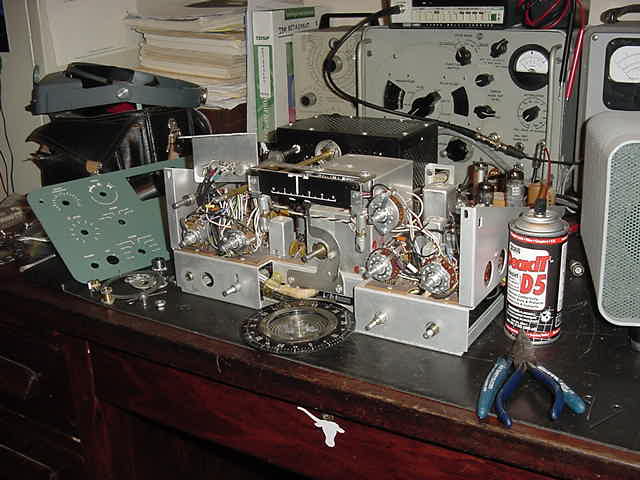
tube socket pin contact, etc. One of the best solutions is to use DeoxIT D5
(made by CAIG Labs) which comes in a spray can with a small plastic tube to
direct the spray. This stuff really works and is available from many of the
electronics supply houses.
Cleaning chassis surfaces
If the radio was kept out in the chicken coop, chances are the chassis could
use some cleaning. There are many cleaners available from the grocery store,
some are better than others, some are not to be used on plastic, and there
is advice everywhere ....from "Don't touch it" to "I ran it through the car
wash first". A very effective cleaning method, involving some time and elbow
grease, uses Windex, an old toothbrush, a clean, lint free cloth, and MANY
Q-tips. Just keep at it until the surface looks clean and let it dry. Works
surprisingly well. Don't forget trying plain old soap and water. Soap and
water cleans up front panels very well and does not disturb lettering like
some chemicals will.
Tube testers
The best "tube tester" is the specific circuit application environment where
the tube is used. Since that requires "known good spares" for substitution
and gets very complex if the tube count is high, there are several types of
tube testers available.
The very smallest and cheapest "supposed tube testers" check only filament
continuity which you can also do with an ohm meter. These testers have no
value what-so-ever ....unless you cut the cord off and want to use it as a
base for a desktop tube display and/or paper weight.
"Emission" testers (most of the Knight, Heathkit, Eico, etc. testers)
connect a DC milliammeter in series with the plate, tie the screens and plate
together, heat the cathode, and measure the current using a selectable AC
plate voltage and load. The tube performs the rectification function. They
don't use the control grid at all and therefore don't measure the tube Gm.
Gm (or transconductance) is the ratio of plate current change to grid voltage
change and is typically one of the tube manufacturer's specifications. These
emission testers do as stated ...check cathode electron emission and will
catch the majority of typical "weak tube" problems and internal shorts. Good
availability and low cost make them very popular. They will not detect grid
emissions problems, they can not be used
to determine quantitatively how close the tube is to its specifications, they
can not be used for tube matching, etc. All that said, it's still a good
"quick, cheap, and close enough" tube tester. I built and used an old Knight
600 for many years.
"Dynamic Conductance" testers (Eico 666/667) supply the grid
with adjustable AC, supply the plate and screen with adjustable AC (the
tube performs the rectification function) and measure the resultant plate
current with a DC milliammeter. The result is a combination of emissions
and dynamic conductance which they call "Merit". Better and a little more
costly than an "Emission" tester but not as good as a "Dynamic
Transconductance" or "Dynamic Mutual Conductance" tester. They also measure
for internal shorts.
The "Dynamic Transconductance" and "Dynamic Mutual Conductance" testers
(all the Hickoks, TV-7s, Heathkit TT-1s, most B&Ks, etc)
are more costly, but they measure the tube "mutual conductance" or
"transconductance" (Gm). They more closely test to the operational environment
by providing selectable -DC bias to the grid, selectable plate and screen
+DC voltages and introduce an adjustable AC signal (the "dynamic" part) on
the grid. These testers have an adjustable plate load and measure the change
in plate current relative to the AC voltage on the grid with an AC
milliammeter. They are excellent for determining tube quality and most allow
direct reading of (or conversion to) tube Gm in micromhos. This is useful for
comparison to the manufacturer's tube Gm specifications. They all measure for
internal shorts.
There are outstanding "Dynamic Transconductance" tube testers for
determining exact tube characteristics (TV-2, etc). These testers
have literally everything metered simultaneously (6+ meters). However, they
are complex, take longer to set up, and as a result, are more prone to
"operator errors". They are generally quite expensive but look impressive.
I personally believe the radio amateur doesn't really need this level of
capability. Only get one of these if you really CAN program your VCR.
All tube testers provide testing for a "range" of tubes.
A TV-7 will test any of the common older 4/5/6/7/8 pin tubes types (like
26, 30, 807, 811A, 1625, etc), octal tubes, loctal tubes, and the miniature
tubes (as well as other types the military used...acorn tubes, pencil tubes,
829B, etc). The last tube data manual (that I know of) is dated January 1962.
If you don't have the latest level, Antique Electronic Supply (AES) has them.
A TV-7 will not test compactrons, used in some ham gear, and newer miniature
tubes unless the test data for these tubes can be found. It will test
everything in any HBR Receiver or Collins S-line. A B&K 747 (solid state
tube tester....ironic, huh ?) will test octal tubes, loctal tubes, miniature
tubes, and compactrons. It will not test the older 4/5/6/7/8 pin tube types.
It will test everything in an HBR Receiver, Collins S-line, any Heathkit
(including the compactrons), and any tubes in other ham equipment including
imported units.
I finally found a very nice TV-7 which I use to test 4 & 5 pin tubes.
However, the one I use most often because it's fast and has a very sensitive
grid emissions/leakage test, is the B&K 747. The B&K has easy setup using
"common" tube sockets and selection lever setup for the rest, has single
control selection lever reset, and has two test buttons for dual section
testing.
Tube testing
Make certain your tube tester is calibrated per the manual.
On simple "emission" testers this involves setting the filament voltage to
the correct level so the "Line Test" indication on the meter is correct. The
more complex calibration procedures involve setting bias levels, meter
balancing, load calibration, leakage/shorts calibration, etc and are covered
in the various tube manuals (SND Tube Sales and others offer copies of tube
tester manuals).
The tester instructions are not kidding when they say the first test should
be "shorts and opens" and if the tube indicates a short, DO NOT TEST FURTHER.
Depending on the type of short, you can damage the meter movement. I have
personally seen many low emission tubes (not enough electron flow from
the cathode to the anode), quite a few filament to cathode shorts (very
common failure), several grid emissions failures (grid saturated with, and
re-emitting, electrons from the cathode), some gas failures (secondary
emissions as the electron flow strikes unwanted internal gas molecules), and
every now and then, an open filament or cracked tube glass.
Micromho meter indications (Gm) are useful to compare to tube manufacturer
specifications if you really want to "get it right". For general use, the
"good/bad" scale is more than sufficient.
A few notes on IF transformers
I've seen several older IF transformers on older rigs which won't
tune up properly. Could be any combination of coil/padder/slug
or mechanical changes over time. Sometimes the IFs which had
the fixed mica capacitor moulded into the base deteriorate over
time due to corrosion and change value (they also develop shorts).
Sometimes the slug breaks or cracks....or this happened before and someone
replaced the slug with "a handy one in the junkbox". Replacing the fixed
capacitor (maybe a slightly different value) to get the
IF to tune up properly may be the solution. By the way, the
correct position for the slugs in an IF is toward
the outside of the transformer (since there are typically two
peaks for each slug). Tuning the slugs towards the inside can
overcouple and widen the IF passband.
Repairing IF Transformers
If you happen to have a defective IF transformer (open/short) all is not lost.
Carefully remove the aluminum can and examine the wiring closely for breaks
under a magnifier. If it's an obvious break/short at the pin, it's easy to
repair with some carefull soldering. If it's in the coil, you may still be
able to repair it. Very carefully scrape a bit of insulation off the coil in
various places with an x-acto blade attached to an ohm meter to determine the
location of the break. The last one I found was at the inside, so I picked a
turn loose at the core and ran a wire from there to the IF transformer solder
pin. Works great, required only a small adjustment to retune and is one heck
of a lot easier than rewinding the coil or finding an exact replacement.
Stiff Tuning
Stiff tuning can often be fixed by relubricating the ball vernier drives.
Even the Jackson Bros vernier drives (especially old ones)
develop something other than smooth tuning due to hardened
lubricant, dirt, dust, etc (feel a slight grinding, backlash, etc).
Taking them apart for cleaning and making sure the correct
pressure is applied to the 4 balls requires care, since those
six "fold-over" tabs control tension via the bronze "waffle
spring/washer" and are not meant to be mashed tight. Too
tight will result in stiff tuning, too loose will result in slipping.
But it does allow you to completely clean the drive assembly.
Soaking in solvent works to some degree. A much easier way,
which works well, is to heat the body of the vernier with your
soldering iron (reflows the grease). If you need more grease
use automotive lithium chassis grease or Lubriplate. To force
the grease into the bearings, fill the coupling with grease and,
with the set screws in place, hydraulically force the grease inside
using a section of 1/4" dia shaft until you see it exiting around
the input shaft.