of ENERGY!
![]() computers,
computers,
![]() light,
light,
![]() space,
space,
![]() weather,
weather,
![]() radio,
radio,
![]() television,
television,
![]() shortwave,
shortwave,
![]() radar,
radar,
![]() engines . . .
engines . . .
![]() and even the sounds of bending paper clips,
TV-VCR remotes and underground pipes!
and even the sounds of bending paper clips,
TV-VCR remotes and underground pipes!
DRRC M
Discovery Resources for Radio Communication
Ormond Beach, Florida 32176
DRRC Edition No. DR100
$2.50
Bulk Discounts Available
You may duplicate sufficient copies of this work for nonprofit use by ONE group or class of fewer than 50 students (or Scouts, etc.) for one semester or project. For commercial reproduction or wider or ongoing institutional use, please email the author to obtain a simple, reasonably-priced license. Thank You!
Dan F. Onley, K4ZRA at [email protected]
The entire idea of using simple audio
amplifiers with various kinds of input devices to "listen
to energy" comes to me straight from a book titled Exploring
Light, Radio and Sound Energy C
with Projects by Calvin
R. Graf, a retired and now deceased U.S. Air Force electronics
engineer. His delightful book (TAB Books 1045-0585, ISBN 0-8306-1758-2,
copyright 1978, 1985) is out of print, but I encountered it first
at a public library, as you might also do.
Calvin's fine book pulled together
for hobbyists and students the simple fact that many different
kinds of energy detection circuits or devices can be connnected
to commonly-available audio amplifiers to let you hear the sounds
of various types of energy. The book included construction details
for suitable amplifiers made from now-obsolete parts as well as
illustrations of vintage off-the-shelf Radio ShackJ
amplifiers. The book also talked of using detection devices such
as selenium photocells, which are now harder to find, and of listening to the internal workings of the earliest LED calculators, now obsolete.
What is NOT at all obsolete is his
premise that you can listen to energy of all kinds, using the
right input circuit or device connected to an audio amplifier.
For every idea written up here, how about a new one of your own!
My main interest in designing this short booklet was to make
it affordable for class and scout groups, so that each experimenter
can have his or her own copy.
I developed this booklet in support
of the T-KIT Model 1252 Portable Audio Amplifier, which has evolved
into a rugged, multi-featured utility amplifier for technicians,
and radio hams as well as experimenters, with much practical usefulness beyond the projects in this booklet.
In preparing this updated booklet
for experimenters of all ages, I started with Calvin's neat ideas,
checked them out, and offer you my experience with them as well
as with experiments with newer technologies which Calvin foresaw
but did not live to tinker with. My deep thanks to Mrs. Graf
for her kindness during my several years of pondering how best
to share her Calvin's practical wisdom and know-how with you!
C
DAN F. ONLEY, K4ZRA
You need not be an electronics buff
to have fun with the ideas in this booklet. You could be a guitarist curious about what else you might do with that practice amp or a Scout leader wanting to show your gang other uses for their
boom boxes!
ANY sensitive audio amplifier connected
to the correct type of "transducer" will let you listen
in on the curious and often exciting "Sounds of Energy."
A "transducer" is any sort of pickup device which converts some kind of energy into audible sounds through an amplifier. The microphone is the most obvious and common transducer, converting voice, music and other sounds into electrical energy which can be amplified and heard more clearly or loudly. Other kinds of transducers can let you use an amplifier to hear the
sounds of the sun, the moon, a storm on the other side of the
globe, the inner workings of computers, underwater creatures .
. . and much more!
"Any sensitive audio amplifier" can be your home stereo, provided that it has jacks for external or auxiliary input and you are willing to haul it around to the right locations for the experiments of interest to you. Other amplifiers such as those designed for musical instruments or public address also will work fine, if you are willing to take them to wherever the most common "Sounds of Energy" (AC line hum) will not drown out what you hope to hear. You can customize a more portable audio amplifier around a kit circuit board module such as T-KIT Model 1550, or you can build and add the nifty T-KIT Model 1252 to your electronics workbench.
The most common (and unwanted) sounds
of unseen energy are all around most of us: the 60 Hz buzz of
AC power lines and wiring, whether overhead transmission lines,
street lamps or simple household wiring. Touch the input of any
audio amplifier, and your body does a great job of "transducing"
the surrounding 60 Hz AC energy into an unmistakable audio buzz!
Fortunately, a simple type of wire
design called a shielded cable permits microphones and many other
kinds of transducers to detect the sounds of energy without the
intrusion of nearby AC 60 Hz wiring.
M
Sensitive, portable audio amplifier
M
Shielded cable
M
Transducers appropriate for the energies you want to hear.
If your "boom box" has
"Auxiliary" audio inputs (for CD, turntable, etc.),
you're in business. Other useful portable amplifiers include
"karaoke" machines, musicians' practice amps, portable
PA amps, or various small amplifiers sold by RadioShackJ.
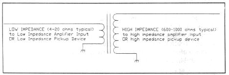
NOTE on "Impedance Matching":
Unless your amplifier includes a
low impedance input (4 to 20 ohms, for example), as does the T-KIT Model 1252, it is recommended for some experiments that you provide a low impedance to match a device such as a speaker or loop antenna to your amplifier. A simple audio transformer will do the trick. Such a transformer may be purchased from Radio Shack or salvaged from a discarded radio. If your amplifier is homebuilt or designed around the T-KIT 1550 module board, you may wish to build in a low-impedance input as a permanent feature of your amplifier.
If you try to use an "amplified
speaker" for these projects, be aware that these boxes (designed for "Walkman" type personal stereos and computers) already have a low impedance input, and that you would need to use the same transformer in reverse to provide a high impedance input for microphones. Even with the transformer, such amplifiers may or may not have enough gain to be useful for experimenting.
The originally-intended use of the
telephone pickup coil for tape-recording phone conversations is
fading as newer telephone technologies take hold. However, such coils have many interesting applications.
First, think of the telephone coil
as your basic "energy stethescope." It even LOOKS a
little like a medical stethescope, doesn't it! You can use this handy pickup coil to listen in very easily on more forms of electromagnetic energy than you may ever have imagined. For example:
"
Computers
"
Ham radio transceivers (microprocessor controlled)
"
Microprocessor-controlled AM/FM/CD radios
"
Fax machines, telephones, copiers
"
Computer peripherals (printers, modems, etc.)
"
Frequency counters
"
VCR/TV remote controllers
"
Quartz electronic watches and clocks
"
Pacemakers
"
Microwave Ovens
. . . and, of course, strong sources
of 60 Hz AC
As you move the pickup coil around
a computer or other micro-processor device, you will hear different
pitches and patterns of sounds depending on clock frequency.
Press even a single key or execute a command, and you'll hear
new sounds of the computer at work. Laptop computers are especially
musical, since there is no AC power involved or metal case to
shield the energy emissions.
The pickup coil will let you hear
some kind of sound made by virtually any electrical device, including:
"
Electric motors
"
Switches
"
Dimmers
"
Automotive electrical systems
The pickup will also detect electromagnetic
energy from other speakers, earphones and even the electronic
audio circuitry in radios and other devices.
While most of the phenomena mentioned
so far are for fun, discovery, and experimenting, there can also
be practical uses for the pickup coil such as tracing AC wiring
behind walls. You also will notice that metal pipes also radiate
AC hum and can be traced behind walls.
A telephone pickup coil consists
of hundreds of turns of extremely thin diameter insulated "magnet
wire." You can make an adequate pickup coil for simple experiments
with stronger energy and RF signal sources by winding as much
thin magnet wire as you can (at least 20-30 feet) around a thread
spool, plastic pill bottle or a 1" length of 1/2" or
3/4" PVC pipe or wooden dowel.
A typical telephone pickup coil has
an inductance of 100 to 150 milli-henries and an impedance
of several hundred ohms, while a coil made of 20 feet or so of
magnet wire has an inductance of about 150 micro-henries
(0.15 millihenry) and a very low impedance of 1 to 2 ohms.
So, if you are making your own pickup
coil, the idea is to use as much of the very thinnest magnet wire
you can find.
Another, larger style of telephone
pickup coil (generally obsolete these days) was used in the early
1980's for computer modems which permitted the user to lay a traditional
telephone handset onto the matching parts of the modem for data
communication. If you find such coils at an electronics surplus
store or swapmeet, they should cost very little and yet will be
excellent audio energy transducers for the projects described
in this booklet.
The Telephone Pickup Coil is convenient and is optimized in design for transducing electromagnetic and low-level RF energy, but ANY coil or small transformer will work to some extent. Experiment! The high-impedance winding of miniature audio transformers comes very close to the performance of telephone pickup coils.
Finally, before discussing next the common microphone as an energy transducer and the familiar problem of microphone-speaker "feedback," try placing the audio pickup coil near the speaker of your amplifier.
The funny-sounding whoop-whoop sound is feedback oscillation caused by the coil picking up the electromagnetic energy in the speaker coil.
Of course, any high-impedance microphone may be connected to an amplifier to create a simple PA system. To use a microphone in practical situations as an audio detection device, headphones rather than a speaker should be used for listening.
Squealing "feedback" oscilllation occurs quite easily when a microphone picks up sound from its nearby amplifier's speaker.
Inexpensive microphones such as those used with portable cassette recorders also can pick up many of the same sounds which you can detect with the telephone pickup, such as the symphony of the sounds of your computer loading a program.
For many applications, any simple
loudspeaker will work quite well in place of an actual microphone,
which is the working principle of intercom systems. When using
a speaker as a microphone, remember that it is a low-impedance
device and should be connected to the low impedance input of an
amplifier such as the T-KIT 1252, or used with an audio transformer.
(See note on page 6).
The most interesting experiments
with audio microphones are those using specially-rigged microphones to hear real sounds beyond normal earshot. Examples are the "Big Ear" microphone with parabolic reflector and the underwater microphone (see mention of "hydrophones" in Chapter
5).
Hear Sounds of the Atmosphere! p.13
Copyright 8
1996. All Rights Reserved.
![]()
Author's Acknowledgement

![]()
Introduction
![]()
Listening to Energy:
Basic Equipment Needed
![]()
1. The "Telephone Pickup Coil"
![]()
2. New Uses for Simple Microphones
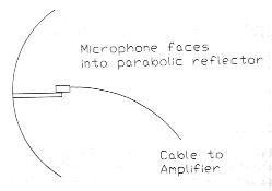
The parabolic reflector concentrates distant sounds to the microphone mounted at its focal point. You may have seen parabolic microphones at sporting events or in detective shows. A suitable reflector can be made from a shallow mixing bowl or a round "snow coaster."
As already mentioned, a small speaker can serve as a suitable microphone for many experiments. Keep in mind that today's stereo headphones contain very small speakers, so don't throw away that last headset you bought just because one channel or the plug went bad. Also, acoustical pickups for musical instruments can serve as interesting transducers for many experiments mentioned in this booklet.
Some Teaser Questions for You!
Why might common electronic components such as resistors or capacitors function as audio pickup devices, able to detect (somewhat faintly) the oscillations within a laptop computer or fax machine? Why might a wirewound resistor work better than a carbon resistor?
Experiment Notes:
Calvin Graf's book had a chapter
titled "The Crystal Video Receiver" in which his love
of and understanding of "avionics" (aviation radio)
was quite evident. He explained his use of the unusual expression "crystal video receiver" in terms of detector circuits used in radar systems.
His idea offers a wealth of experimenting fun especially for those who enjoy getting out and about on foot, or by bicycle or vehicle, finding places where there are strong VHF signals. Take a look at the circuit below, and you see how easy it is to turn any sensitive audio amplifier into a simple VHF broadband signal detector which needs no tuning.
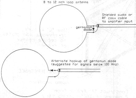
The diode must be germanium, not silicon, such as 1N34A or 1N270.
What we have here is a variation
of the classic "crystal set" radio receiver. For portability, the simple wire loop serves as both antenna and very broadband tuned circuit capable of detecting strong and nearby VHF radio signals.
A crystal detector is more responsive
to AM (amplitude modulation) signals than to FM (frequency modulation), but it is possible to hear nearby FM or TV broadcast signals as well as signals from CB radios, emergency vehicles, walkie-talkie's, garage door openers and many other RF sources. You also will be able to use this loop to hear many of the same emissions listed on page 7 for the telephone pickup coil.
In the previous chapter, we explored using a germanium diode detector with a short loop antenna to hear nearby VHF radio signals. It is also possible to hear interesting atmospheric sounds and perhaps certain VLF (very low frequency) radio signals with a larger loop antenna, with no diode used. The loop antenna discussed in this chapter is designed to receive in the 50 Hz to 12 KHz spectrum.
Calvin Graf suggests the large loop
antenna for listening to lightning "whistlers," the
"dawn chorus" and other atmospheric energy which may
sound like pops, hiss or plain old "static"! He also
mentions the Omega navigational system which uses a worldwide
network of VLF radio stations transmitting on 10.2, 11.33 and
13.6 KHz but does not raise high hopes that you will hear them
with this kind of setup. Since the Omega system fixes (1-2 miles) are not at all as precise as satellite GPS technology, its future may be questionable.
The larger the loop, the more sensitive your setup may be, if designed correctly. However, portability
is an essential design factor, because you need to do your listening somewhere away from AC power lines.
Figure 4.1: Large Loop Antenna
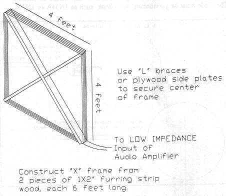
Mr. Graf proposed a square loop measuring
4 feet on each side, consisting of 5 complete turns of hookup
wire around a wooden frame constructed of inexpensive 1x2"
lumber, often referred to as "furring strips." A suitable frame could also be constructed from PVC plastic pipe and fittings. Notches should be cut with a saw at all 4 ends of the "X"
to permit spacing the 5 turns of wire evenly about 3/16"
apart.
It is important to remember that
a loop antenna is highly "directional," which means
that it must be pointed correctly toward a signal source for maximum
signal strength. The ENDS of the loop (not the broad 4X4'
sides) provide maximum signal strength.
You may wish to devise a portable
mast to suppport your 4X4' loop antenna when you have other things
to do besides carrying it around!
Unless your amplifier includes a
low impedance input (4 to 20 ohms, for example), as does the T-KIT Model 1252, it is recommended for best results that you transform the low impedance of the loop before connecting it to your amplifier.
See page 6.
Because many of the sounds you'll
be listening for are related to lightning discharges aound the
globe, it will be worth your while to study up on exactly what
lightning is, using any reputable science text or encyclopedia.
In the meantime, the following may be helpful:
Lightning is a natural, shortlived,
highcurrent electrical discharge in the atmosphere. The
path length of the discharge is normally several kilometers.
The cumulonimbus clouds of thunderstorms are the most common producers of lightning, but it is also produced by cumulus, stratus, and other kinds of clouds, including
snowstorms, sandstorms, and clouds over erupting volcanoes. Lightning can also occur in clear air within a few kilometers of a thunderstorm. More than half of all discharges occur within a cloud. The rest generally take place
between clouds and the ground, with occasional cloudtocloud or cloudtoair
discharges. A rare discharge called an upflash, between large
storms and the clear air above, may be caused by electrons cascading down from the ionosphere. At any one time about 2,000 thunderstorms may exist worldwide, producing lightning flashes at a total rate of 100 per second . . .
Cause
Before lightning can occur, a charge
separation large enough to cause electrical breakdown of air must develop. Thunderstorms are generally negatively charged at the base and positively charged in higher regions. One theory holds that the principle mechanism for separating electric charge is the vertical separation of larger charged droplets of water or ice (raindrops, hailstones, and so on) from differentially charged smaller droplets, as a result of their different settling velocities within a cloud. Another theory holds that small cloud particles and droplets are the principal charge carriers, and that the main mechanism for the separation of charge is the variable convective air motions within a cloud, which carry some particles upward
and others downward.
Occurrence and Formation
Discharges between clouds and the ground cause the greatest destruction. Most are initiated from the negatively charged base of a cloud, but a few (and often more powerful) discharges are initiated from positively charged higher regions, most commonly in winter storms. Strokes initiated from the ground are rarer, the more frequent being from positively charged tall structures or mountain peaks; negative upward strokes are rarest of all.
The most familiar lightning strokes
are the negative cloudtoground flashes. They start
near the base of a cloud in the form of an invisible discharge
called the stepped leader, which moves downward in discrete, microsecond steps about 50 m (165 ft) long. The stepped leader is believed to be initiated by a small discharge near the cloud base, releasing free electrons that move toward the ground. When the negatively charged stepped leader approaches to within 100 m (330 ft) or less of the ground, a leader moves up from the groundespecially from protruding objects such as buildings and treesto meet it. Once the leaders have made contact, the visible lightning stroke, called the return stroke, propagates upward from the ground
along the path of the stepped leader. Following the return stroke, several subsequent strokes can occur along the original main channel in less than a second. These strokes continue until the charge center in the lower part of the cloud is eliminated. The explosive heating and expansion of air along the leader path produces a shock wave that is heard
as thunder.
Ball Lightning
Ball lightning, a littleunderstood
phenomenon, is generally spherical, from 1 to more than 100 cm
(0.4 to more than 40 in) in diameter; it usually lasts less than 5 seconds. The balls are reported to move horizontally at speeds of a few meters per second and to decay silently or with a small explosion.
by William R. Cotton
Copyright 8 1993 Grolier Electronic Publishing, Inc.
Bibliography: Barry, J. D., Ball Lightning and Bead Lightning (1980);
Hart, W. C., and Malone, E. W., Lightning and Lightning Protection (1979); Clouds, 2d ed. (1971); Salanave, L. E., Lightning and Its Spectrum (1980);
Uman, Martin A., All About Lightning (1986)
and The Lightning Discharge (1987).
Lightning "Whistlers"
A "whistler" is a unique
atmospheric radio noise ("spheric" for short) resulting
from a lightning strike and audible as a changing-pitch tone even with our simple amplifier-antenna setup. Not all lightning strikes result in whistlers, and it has been found that whistlers follow the lines of the earth's magnetic field. Whistlers, or descending whistling sounds occasionally heard on radio amplifiers, are meteorological phenomena useful in research on electron densities of the upper ionosphere. The sounds, which have frequencies between 300 and 30,000 Hz, repeat rhythmically and become longer and fainter as they progress. Whistlers originate as lightning discharges
in the atmosphere. The associated, inaudible electromagnetic radiation travels from one hemisphere to the other, nearly 12,500 miles high in the atmosphere, along lines of magnetic force and is reflected in the opposite hemisphere at the latitude corresponding to that at which the radiation was produced. Because the higherfrequency
waves are faster, they reach the amplifier first; the softening, repeated sounds are caused by repeated reflections that have been dispersed and absorbed.
The frequentness of whistlers you
might hear depends also on the same sunspot cycle which affects
shortwave radio transmission paths ("propagation").
If radio conditions are good, the more whistlers you can hear.
Time of day is also important for whistler-monitoring, with the activity peaks occurring between midnight and dawn when you'd rather be sleeping. (See Chapter 6 regarding cassette recorders).
The Graf book describes a phenomenon called "Dawn Chorus," natural atmospheric RF signals not associated with lightning. This phenomenon consists of rising tones and gets its name from the sounds of birds in the English countryside at dawn, also accompanied by a distinct rush of noise. (Note: I believe I have encountered this as a rather unique "musical roar" for a few minutes before/during daybreak while operating on the lowest amateur radio band (160 meters, 1.8-2.0 MHz.)
Finally, it is interesting to recount Calvin Graf's story of how lightning whistlers were first discovered by German scientist H. Barkhausen during World War I. To try to eavesdrop on Allied telephone conversations, he tried driving two metal stakes into the ground and connecting them to the input of an audio amplifier. Instead of human voices, he heard lots of the atmospheric sounds today known as whistlers. Graf's book does not state how far apart the metal ground pipes were, but trying to recreate Barkhausen's experience could be a great experiment in itself!
Geomagnetic field of the Earth
The Earth has a magnetic field, which
originates primarily within the Earth's interior, although a small
part is produced by the planet's ionosphere and magnetosphere.
About 90 percent of the geomagnetic
field can be represented by the magnetic field that would be produced by a bar magnet located at the Earth's center and inclined at about an 11 degree angle to the Earth's
rotational axis.
Distribution
At a given point on the Earth's surface,
the geomagnetic field can be represented by its intensity (F);
its dip or inclination (I), the downward deviation of its direction from the horizontal plane; and its
declination (D), the eastward deviation of the horizontal component
of geomagneticfield vector from true north.
The geomagnetic field is vertically
downward (I = 90 deg) at the north magnetic pole (76 deg north
latitude, 100 deg west longitude in 1975), and vertically upward (I = 90 deg) at the south magnetic pole (66
deg south latitude, 139 deg east longitude in 1975). The surface intensity of the geomagnetic field is smallest at the magnetic equator (a plane midway between the magnetic poles) and increases toward both poles.
The geomagnetic field has been measured at many points on the Earth's surface and also, with aircraft and artificial satellites, at points above it. These magnetic surveys have revealed in fair detail the distribution
of the geomagnetic field on the surface and in the space around
the Earth. They have also demonstrated that the geomagnetic field consists of, in addition to the main magnetic field, relatively small local magnetic fields of various scales that are closely related to the geological structures near the Earth's surface.
For example, igneous rocks are much more strongly magnetized
than sedimentary rocks; therefore the geomagnetic field near
such igneous rock bodies as volcanoes is systematically disturbed.
Detailed magnetic surveys can thus often identify subterranean
magnetized geologic bodies and determine their approximate structures.
Research suggests that movements of the fluid rock in the Earth's
outer core have resulted in irregular changes in the Earth's magnetic
field.
Variation
The main geomagnetic field is changing
with time. Its intensity has been continuously decreasing by 6
percent every 100 years, and the regional positive or negative
anomalies are drifting an average of
about 0.2 deg west per year. These secular variations have been directly observed only during the last 100 years. Paleomagnetic analysis of natural rocks, however,
has revealed not only the secular variations of the geomagnetic
field over a long geologic time, but also frequent complete reversals of its distribution pattern during comparatively
short periods (2,000 to 10,000 years). This polarity reversal
is the most conspicuous characteristic of the geomagnetic field.
Dynamo Theory
A theoretical interpretation of the
mechanism that produces and maintains the main geomagnetic field
must explain its remarkable variations as well as its intensity
and other characteristics. The most plausible theory is known as the dynamo theory. Developed by British physicists W.M. Elasser and Sir Edward Bullard, it attributes the Earth's magnetism to currents flowing inside its fluid outer
core, and to the conversion
of this mechanical energy into electromagnetic
energy. According to this theory, the field is maintained by
the selfsustaining dynamo action of the core, which is presumed to flow in such a pattern that the electric current induced by its motion through the magnetic
field sustains that field. The separate source of energy needed
to move the core is generally assumed to be tidal energy or heat.
Ionosphere and Magnetosphere
About onethousandth of the geomagnetic
field is caused by electric currents within the Earth's IONOSPHERE,
located at about 100 km (60 mi) above the surface. As the atmosphere at this high level becomes
ionized and systematically moves in the presence of the main geomagnetic
field, electric currents are forced to flow within the conductive
ionosphere by a dynamo action.
As both the electric conductivity and
the dynamic motion of the ionosphere are controlled mainly by
solar radiation, the small magnetic field produced in this way
varies regularly on a daily basis.
The electromagnetic interaction between
the main geomagnetic field and the SOLAR WIND also causes electric
currents within the Earth's MAGNETOSPHERE by a dynamo action.
These currents in turn produce about one fivehundredth
of the geomagnetic field. As the solar wind varies markedly over
time, the magnetic field produced in the magnetosphere also changes considerably, often resulting in MAGNETIC STORMS.
C by Takesi Nagata
Copyright 8 1993 Grolier Electronic Publishing, Inc.
Bibliography: Jacobs, John A., ed., Geomagnetism, 3 vols. (198789);
Matsushita, Sadami, and Campbell, Wallace H., eds.,
The Physics of Geomagnetic Phenomena, 2 vols. (196768);
Press, Frank, and Siever, Raymond, Earth, 4th ed. (1986);
Rikitake, Tsureji, and Honkura, Yoshimori,
Solid Earth Geomagnetism (1986).
Certain light-sensitive devices connected
to an audio amplifier will produce some sort of audible sound
when the light source is altered, removed, or turned back on.
Such devices include solar cells and various light-sensitive
diodes such as an infra-red receiving diode. One practical problem
today is that the classic light detector is becoming hard
to find: the venerable selenium photocell, in contrast
to the more common silicon solar cell or CdS photocells. However,
you may find a useful cell at an electronics store, or salvaged
from a discarded "solar powered" calculator.
With a suitable cell connected to
your amplifier, it is possible to hear a variety of sounds when
the cell is exposed to a candle flame, passing headlights, strobe
lights, lightning, TV pictures and other sources of varying light
intensity. Sunlight will produce a steady hissing sound. Remember
that light sources are not making audible sounds. Rather, the
light-sensitive device changes electrical characteristics (voltage
output or internal resistance) in step with changes in light intensity,
and these changes are detected and amplified as audio energy.
If the photocell you are trying just doesn't seem to be doing anything, try putting a small battery in series with it. In fact, a CdS cell in series with a 9V battery becomes an impressively sensitive light-sound transducer.
You will want to use a low impedance
amplifier input for this.
The Graf book also proposed using
a concave magnifying makeup mirror set up to amplify the light
focused on the photocell and even proposed using that setup to
"listen" to the moon and to observe the effect of "modulated"motorcycle and train engine headlights.
The more you know about practical
electronic circuits, the more amazed you will be at how this easy experiment works! Connect a short piece of steel or iron wire
(not copper) directly across the input of your audio amplifier.
Six inches of wire is good but even a stretched out-paperclip
will work. The amplifier background noise is sharply reduced
because we have created a very useless direct short, right? First,
don't worry: this will not damage the amplifier. Now, listening
carefully to the quieted amplifier (perhaps with headphones),
move a small magnet near the steel wire. You'll definitely hear
clicks and thumps if the magnet touches the wire, but the really
interesting sound is the whoosh or hiss audible when the magnet
moves close to the wire. This is the sound of "shifting
magnetic domains," also called Barkhausen Noise. Any encyclopedia will give you plenty of information about magnetism.
Connect the telephone pickup coil
(Chapter 1 experiments) to your amplifier, letting the pickup
sit on your worktable so you can manipulate objects near the pickup.
First, just rub a couple paperclips together within 1/2"
of the pickup coil. You will hear very distinct sounds. Now
try rubbing the clip against various plastic, wooden, aluminum
or copper objects, and you will hear nothing. Using either your
fingers or pliers, start gently flexing a paperclip or steel wire
as close to the pickup coil as possible. You will easily hear
Barkhausen noise as you flex the wire, provided that your pickup
coil is oriented so as not to pick up AC electrical hum. If you
break the wire, you'll hear a distinctive snap!
The practical value of the Barkhausen
effect is that it underlies technologies used for nondestructive
testing of vital steel components in industry and construction.
The Graf book included a chapter
("Small Loop Antenna") in which he discussed using a
2'' telephone pickup coil, which seems no longer
container, cardboard tube, PVC pipe,
etc. Secure the turns with duct tape, and solder a shielded audio
cable to the two ends of the coil.
Mr. Graf's suggested uses for such
a coil consisted of tracing underground water pipes and listening to subway trains passing below you. Pipes can be located by this method because they re-radiate harmonics of the surrounding AC power lines. Such a coil will also detect lightning up to about 25-35 miles away.
Most interesting to me was what happened when I connected the T-KIT Model 1252 amplifier to a simple 23' long shortwave ham radio antenna. Voila C
instant shortwave receiver, as long as you don't mind hearing
two or three strong stations all at once! I noted it was important
to use the low impedance input of the amplifier; the AC hum was
deafening when I tried the high-impedance input. Also, the signals were much stronger with the ground side of the coax feedline connected to the ground of the amplifier. I tried adding a germanium diode to this setup, but it did not change or improve reception.
Why did this happen? It's fairly
simple, actually. In each shortwave band, there are several stations with extremely strong signals. In fact, 2/3 of the circuitry in any "real" receiver is for "selectivity," put there to reject other unwanted signals. Connecting an antenna directly to a sensitive amplifier results in what might be called a broadband (very!) "autodyne" receiver, a simple circuit
used briefly in the 1920's.
For fun, I next connected an antenna tuner (used for matching ham transceivers to various antennas) between the amplifer and the antenna and was able to play with the knobs to tune in my choice among Radio Marti, Radio Canada International and one of the many religious broadcast services.
Unless you get interested in building tuneable circuits between the antenna and the amplifier, I doubt that you would gain much control over tuning which shortwave stations you may hear with this kind of setup. However, this phenomenon could get you or a friend interested in discovering just how easy it is to build and enjoy a practical shortwave receiver. [The T-KIT catalog features a nice variety of inexpensive SWL ("shortwave
listening") radio kits.]
With this setup, I occasionally heard
also a distinctive "frying" sound,
the sound of certain auroral activity which might be detected with the 4' loop antenna.
There is great listening possible
underwater, whether in a lake, river, ocean or your home aquarium. All you need is a "hydrophone," which is a transducer/microphone specifically designed for underwater operation. Building your own hydrophone should be a do-able hobby project if you have access to the how-to information. Mr. Graf settled for ordering a military surplus hydrophone from Edmund Scientific Company and offered no homebuilding ideas!
The final chapter of the Graf book
describes a "Rain Alert Microphone," which consists
of a speaker mounted midway inside a plastic bucket, mounted bottoms-up on the roof or just out in the yard. This project evolved not because of any preoccupation with a bit of rain at home but from the Air Force's need for rain alerts during manned rocket sled tests in New Mexico during the 1950's! It works very well and also lets you hear all else going on in your neighborhood, whether you want to or not.
A cassette recorder can help you
enjoy the experiments in this booklet in several ways. Of course,
a tape recording is always handy for reviewing or sharing what
you heard. You can set up a cassette recorder to switch on if
you start hearing some phenomenon you want to record. OR, the
recorder itself can be your all-in-one monitoring device for certain
projects. For example, you've build the 4' loop antenna to try
listening for lightning whistlers or other VLF phenomena. You
could set up your antenna in the ideal place at the ideal time,
plug it directly into the microphone input, and start recording
for as long as the tape will permit. Later, you can listen to
the tape while doing something else. If something interesting
happened during the monitoring session, you'll hear it and also
be able to replay it.
This booklet, along with Exploring Light, Radio and Sound Energy by Calvin Graf, gives you the basic idea of what kind of experimenting can be done with a simple audio amplifier. Using my own curiosity discovery of how well strong shortwave signals can be received (see 6C above) as an example, try out your own ideas. What might you hear if you hook up to a countryside fence wire, the chain link around your back yard, your TV antenna, or that weird-looking coil you got free at the flea market? What might a laser pointer sound like? What kind of transducer would you use to detect a laser beam? Could you design your own hydrophone? How would you listen to small insects? To your own heartbeat? What would you hear if you connected a small DC hobby motor to the amplifier input and spun the shaft with your fingers? Can you hear the signal from your garage door opener or cellular phone?
What method would you use for finding
hidden "bugs"?
Conclusion
This whole notion of "Listening
to Energy" was inspired by the Calvin Graf book and was accepted
into the introductory lineup of T-KIT by TEN-TEC, now a formidable
electronics kit line which now includes a variety of VHF ham radio
transceivers and transverters. This kit concept resulted in the
engineering of the Model 1252 T-KIT Utility Audio Amplifier, perhaps the most versatile and practical audio amplifier of its kind ever designed.
While the Model 1252 is a fine product, we have tried to make it clear that it is not required for these experiments.
In releasing Model 1252 for sale,
TEN-TEC had to make a very simple choice: provide a minimal amplifier and shop for lots of accessory "goodies" to make many experiments instantly convenient, OR: provide you with a quality,versatile audio amplifier which surely will outlive your interest in the experiments we have suggested. We hope you like our choice and will enjoy the experimental possibilities of "Listening
to Energy."
Listening to Energy
Project Notes