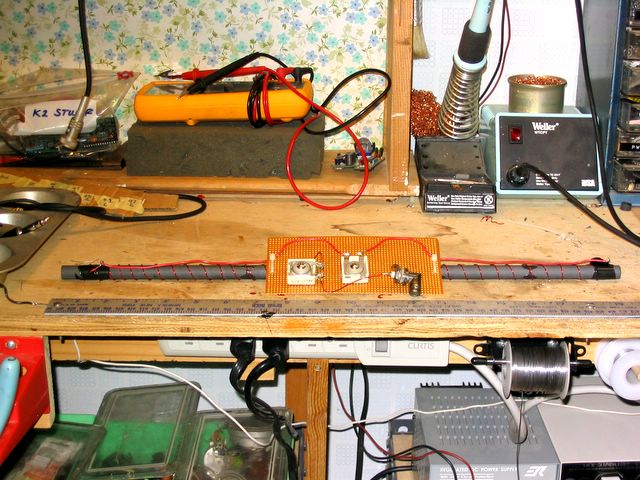
Here is the 160-meter ferrite loop antenna
before it was inserted in a PVC enclosure. The rod was made by
epoxy gluing six 3-1/2" ferrite rods together (sold by KE9PQ on Ebay),
for a total length of 21" (53.3 cm).
I held them in position for gluing by simply placing them in a piece of
angle aluminum lined with waxed paper.
The main coil has 37 turns, and is resonated at 1825 KHz by a 400 pf
trimmer in parallel. The other trimmer is 1500 pf and is in
series with the link (see below).
|
|
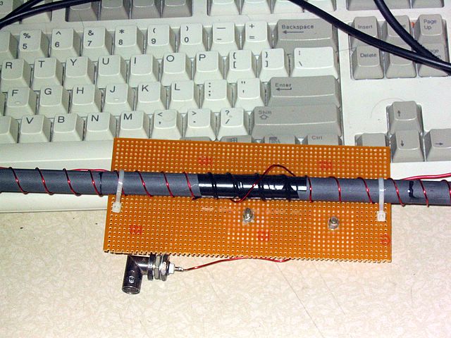
The other side of the board, showing the 1-turn
link. There should be no connection between the link and the main
coil.
The easiest way to tune it is to connect an antenna analyzer such as
the MFJ 259B to the link and adjust both trimmers for minimum SWR.
It was possible to adjust the capacitors for an indicated SWR of 1:1 on
the MFJ analyzer. Tuning is VERY sharp, with gain starting to drop off
noticeably 10 KHz
away from the center.
The gain is quite low, of course, and I use a two-stage
external preamp as well as turning on the preamp in the K2 in order to
make the overall signal strength about the same as that on the inverted
L.
|
|
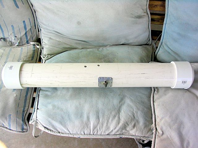
Here is the antenna installed in a PVC
tube. The holes are for tuning the capacitors and will be covered
by tape in the final installation. The rod is supported inside
the tube with some foam material.
The end caps are NOT glued on! I put some silicon grease on the
ends and tapped them into place.
|
|
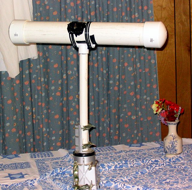
Now the whole thing is ready for mounting.
The black gunk is 'liquid electrical tape', used to prevent water from
getting in around the connector mounting. The large tube just
sits on a cut-down 'T' fitting, held in place by large cable ties.
|
|
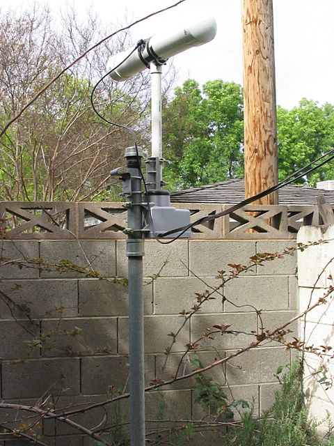
The antenna and rotor mounted on the clothesline
pole in my back yard. I chose this location because it is away
from power lines, houses, and the inverted L. However, the pole
in the background carries some telephone wires, and I suspect that the
null depth is compromised somewhat by re-radiation from these
conductors.
|
|