K2VCO 4CX1000A RF Linear Amplifier

This amplifier is finally more or less finished. The intention is to have a 1500-watt output, brick-on-the-key rated amplifier, usable for all modes -- although the chances of me operating any mode other than CW are small. It covers the 160 through 10 meter amateur bands.

Many commercial amplifiers are limited in their ability to put out continuous power by the size and weight of the plate transformer. One solution is to use a switching supply, but that is beyond my competence. So I've taken the brute force approach and used a really big conventional transformer in a separate power supply unit. It can happily sit on the floor!

I don't pretend that this is the nicest amplifier described on the web -- far from it (if you want to see really impressive work, look at W7RY here, or W8ZR here or WD7S here)  -- but I thought others would be interested in seeing how one ham, who isn't an engineer or a machinist (and who is sometimes lazy and impatient) approaches the job of building something from scratch. In my opinion, this is the essence of amateur radio. It is in every way, a learning experience!

Circuit description
The amplifier is a class AB1 grid-driven design. The input circuit is a simple pi-section low-pass filter that cuts off around 30 MHz. It uses the input capacity of the tube as its output capacitor, thus canceling the effect of this capacity on the higher bands, without needing to be switched in and out. There is a 50-ohm 100 watt non-inductive resistor from the grid to RF ground to provide a load for the driver. This circuit provides a close to 1:1 SWR to the exciter on all bands. I estimate that about 25 watts of drive will develop enough RF voltage across the resistor to drive the amplifier to full output.

Since this is intended to be an all-mode amplifier, I was concerned to have regulated bias and screen supplies for best linearity. I also wanted the appropriate protection for these somewhat delicate elements (the tube data sheet claims that the grid has a dissipation rating of 0 watts). These functions, plus others like the required 3-minute warmup timer, are provided by the G3SEK Tetrode Boards. The Tetrode Boards also provide for T/R sequencing, but the relays provided do not support fast QSK. I used a simple circuit with a fast coaxial relay in the input (see the RFK-6396 relay here) and a Jennings RJ-1A vacuum relay for output. These relays switch in about 4 ms, so as long as the driver provides the appropriate delays after key-out and after the end of RF -- the Elecraft K3 that I use does -- no sequencing is needed. The QSK system also actuates the Tetrode Boards' grid bias switching to cut off the tube completely while the key is up.

The plate circuit is a conventional pi-network. Plate voltage is about 3.2 kV under load, a little bit high for this tube, but I don't forsee any problems. I computed a plate load impedance of 1815 ohms using the load line from the 4CX1000A data sheet following the procedure expalined by G4AXX here (I did need to extrapolate a little to account for the high plate voltage).

Pictures
The massive power supply. Don't drop this on your foot! It includes a 2400V 1.5A ICAS Dahl transformer, which should supply 800 mA at 3.2 kV under load all day long. The back (not visible) is made of perforated metal for air intake. Total filter capacitance is 30 uF at 4050V and the four bridge arms are made of 5 6A10 diodes each. Power supply
Here is the chassis at an early stage of construction. The cutout at the lower right is for the tube unit (see next picture). The panel seen here is actually a subpanel; the front panel will be 3-1/2" in front of it. There will be 2" of clearance underneath the chassis. The main elements of construction are 1/8" aluminum sheet, 1/2" square rod, and 3/4" x 1/8" angle stock.

I don't pretend to be an expert metalworker, and everything is done with hand tools except for a handheld jigsaw and a drill press.

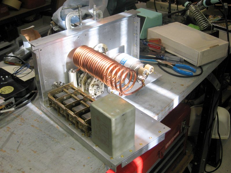
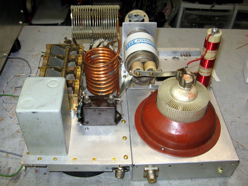
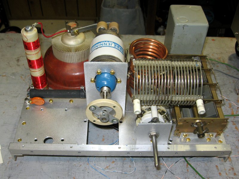
Nice tank coil, isn't it? Too bad it didn't work! This layout made the bandswitch leads so long that it wasn't possible to get a low enough inductance on 10 meters. The new tank appears in a photo below.
Chassis
The tube unit, comprising the input circuit, tube and socket, plate RF choke, blower, and T/R relays. I plan to use a piece of supercharger hose to conduct hot air from the tube to the outside of the enclosure.

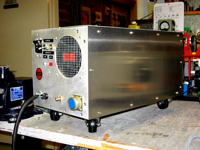
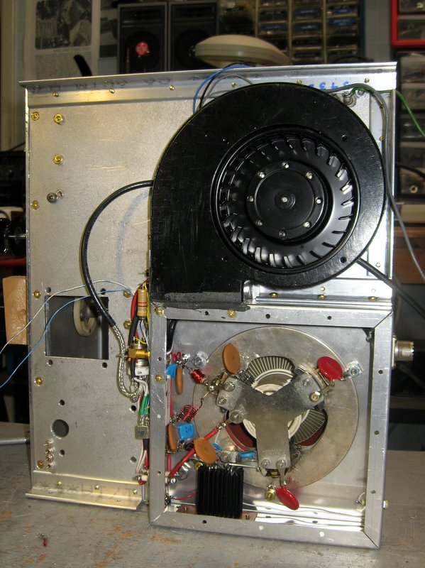
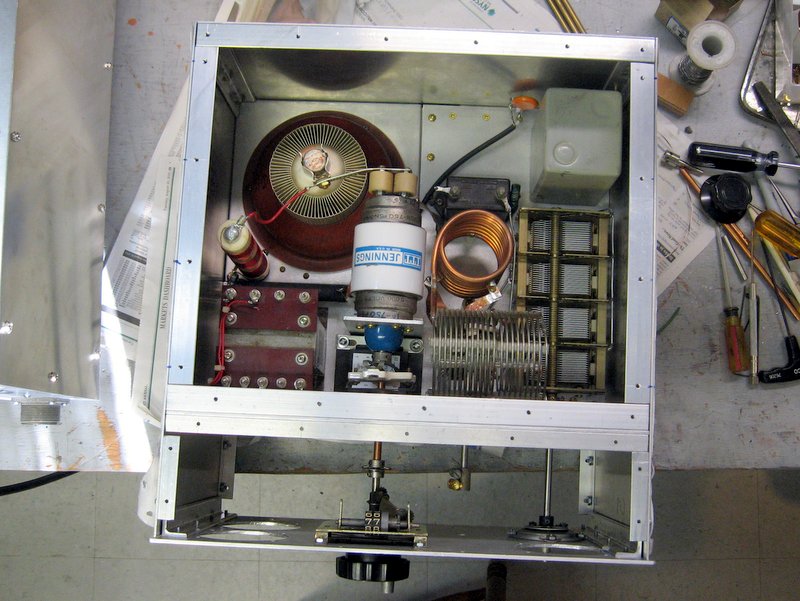
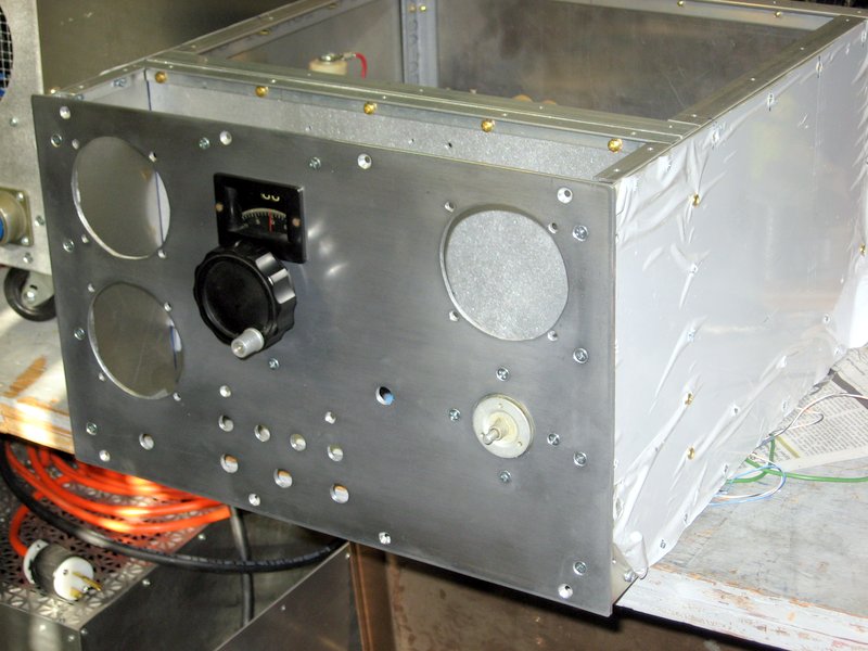
The blower is a bit more capable than needed, but you can't have too much air! I only hope it will not be too noisy.
Tube unit
This is the tube unit viewed from below. The large black object at the bottom is the 100 watt noninductive swamping resistor in its heat sink. It is directly opposite the air supply from the blower, so it will stay cool.

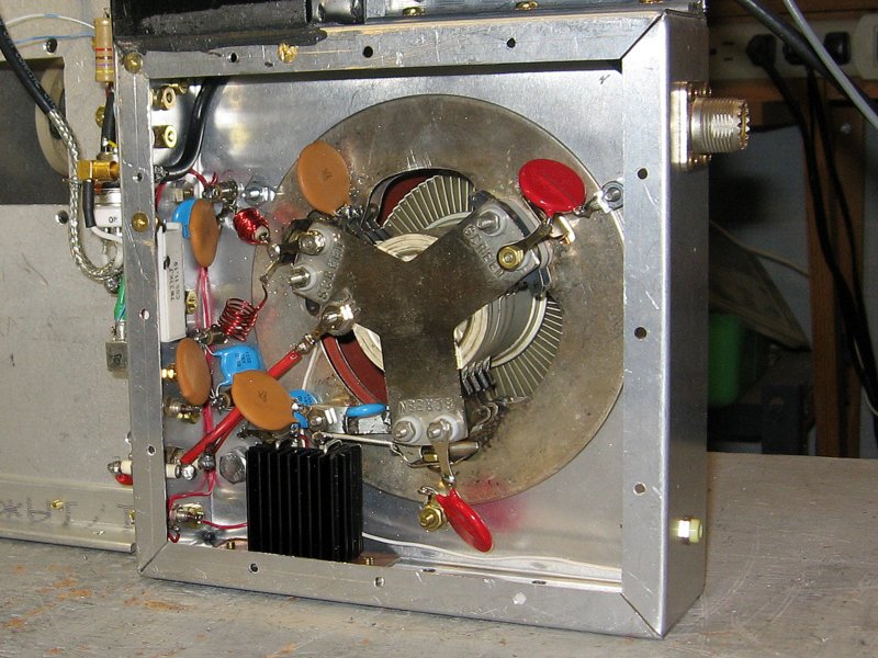
There are two small coils to the left of the socket: the lower one is the inductor in the pi-section lowpass filter, and the upper one is an RF choke wound on a resistor that is in series with the screen. The socket has a built-in bypass of 1500 pf. The large discs connected to the screen terminals are not capacitors -- they are MOVs to protect the driver in the event of flashovers.

I found that a bypass capacitor of 0.01 uf on the cold side of the swamping resistor and a similar capacitor in series with the input were not sufficient to provide a low enough impedance on 160 meters. In order to get a 1:1 SWR to the transceiver, I added 0.1 uf capacitors in parallel. Just to be sure, I did the same with the screen bypass.
Inside tube unit
This is how the tube unit fits under the chassis. The bottom plate will have a hole for the air intake. Underside of chassis
In order to tune up the tank circuit, I needed to be able to set the vacuum tuning capacitor precisely. So I temporarily mounted a counter dial on the subpanel and made a calibration chart for the capacitor. I used the very accurate AADE LC meter to measure the value of the capacitor at every 5 divisions of the dial. I also recorded the dial readings for the calculated values of capacitance for each band. Temporary dial
I used this setup to find the correct positions for the tank coil taps for each band. First, I used G3SEK's Excel spreadsheet (you can download it here) to calculate the pi-network values for a load impedance of 1815 ohms.

Note: it is important to calculate the impedance using the load line, because the usual approximation  -- RL= (Ea/Ia)/k where k = 1.5 to 1.7 for class AB -- is very far off (at least it was in my case).

I measured the inductance of my Ameritron RF choke (225 uh) and various stray capacitances to enter into the spreadsheet, using the AADE meter. This is important for accurate results.

Then I connected a 1815 ohm resistor from the tube plate to ground (all of this with power not connected, of course). I connected an antenna analyzer to the amplifier output. It will show a 1:1 SWR when 50 ohms is transformed to 1815 ohms.

For each band, I set the tuning capacitor to the appropriate value given in the spreadsheet, and located the point on the coil that gave minimum SWR. Iteratively adjusting the loading and tuning capacitors brought it to 1:1. When the point of 1:1 SWR coincided with the calculated value of capacitance, I fixed the tap in place.

This was easier to do than to explain. The hard part was working in such close quarters with the coils and the switch!
Setting coil taps
Here are the assembled G3SEK Tetrode Boards, ready to go! This unit along with several large resistors and a transistor on a big heatsink, make up the regulators and protective circuitry for the amplifier. All of these components will go between the front panel and the subpanel. The top and bottom covers of this space will be made of perforated material so that all of these components can be convection-cooled.
G3SEK Tetrode Boards
The original tank circuit would not provide the correct impedance transformation on 10 meters, because the layout made it impossible to get a small enough inductance on 10 meters. So I redid the tank circuit as you see here.

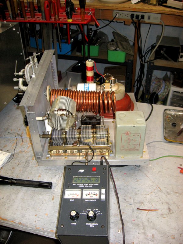
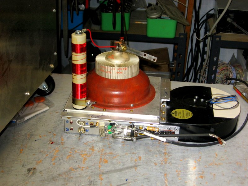
Instead of trying to use 3/16" tubing for the 80 through 10 meter portions, I used it only for 20 through 10. The Airdux coil is used for 160, 80 and 40 meters. It is no. 12 wire, which might be a bit small on 40. I decided to try it and see.

Yes, the coil is made of two chunks of Airdux spliced together. After I see how it works on 40, I'll think about replacing it (but read Robert M. Pirsig's "Zen and the Art of Motorcycle Maintenance" to see why this is OK).
Back view, showing new tank circuit
Here's the front view of the chassis. The screen supply transformer will go in front of the RF choke, and another small transformer for grid bias and QSK relay power in the hole in front of the vacuum capacitor. Front view
The little toroid next to the 160 meter padder capacitor is the safety choke across the amplifier output. It drains the charge from the blocking capacitor and prevents the full plate voltage from appearing on the antenna if the blocking capacitor should develop a short. Many commercial amplifiers use a receiving-type choke rated at 300 mA here; but I wanted to be sure that the power supply breakers would pop if the blocking capacitor shorts.

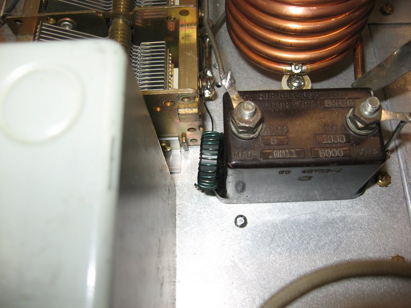
The choke is wound with no. 18 wire on a ferrite core. Theoretically it will have a high enough impecance on 160-10 meters so that it won't burn out. We'll find out!

Incidentally, I used the mica padding capacitor instead of the usual ceramic doorknob because it is able to pass a large current without heating up and changing value, as sometimes happens with the doorknobs.
Safety choke
I have test-fitted most of the parts for the enclosure here. There are lots of parts that will go in between the subpanel and the front panel, including the Tetrode boards.

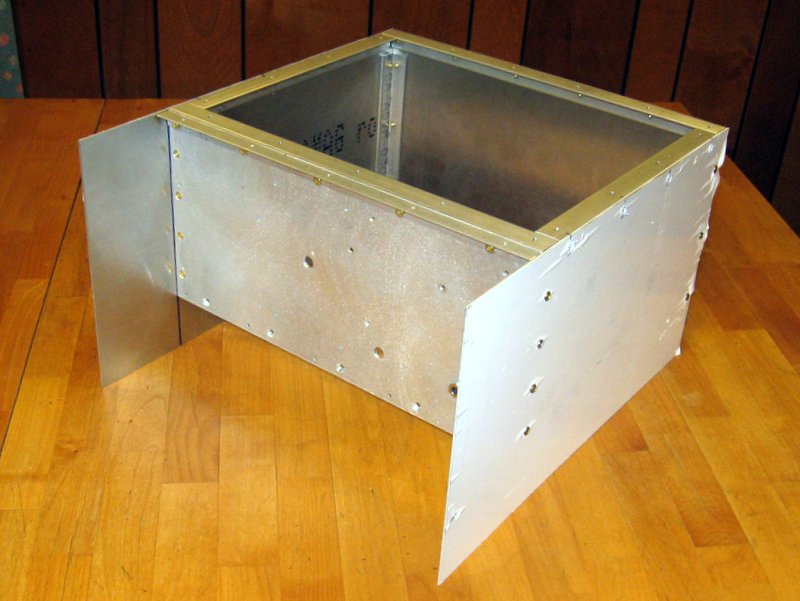
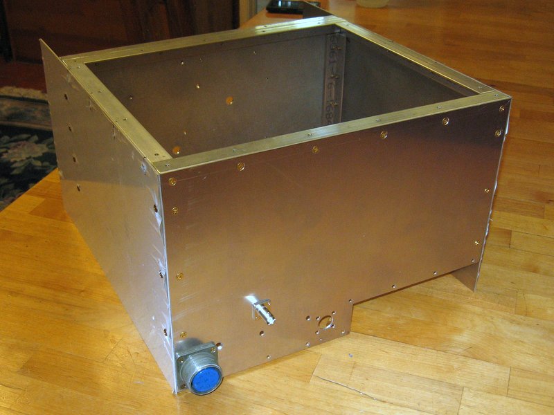
The top, bottom, and sides are 1/16" aluminum.
Enclosure
Here's the back of the enclosure. The BNC-like connector is actually an MHV connector for the coax that will supply the 3200V plate voltage. The other power supply interconnections are made to the blue socket at the bottom.
Enclosure back view
Starting to put things together! It almost looks like it will be an amplifier. Side view.
Here is another view with the front panel temporarily attached. All that space between the panels will be filled with the control circuits, screen regulator parts, etc.

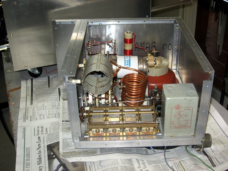
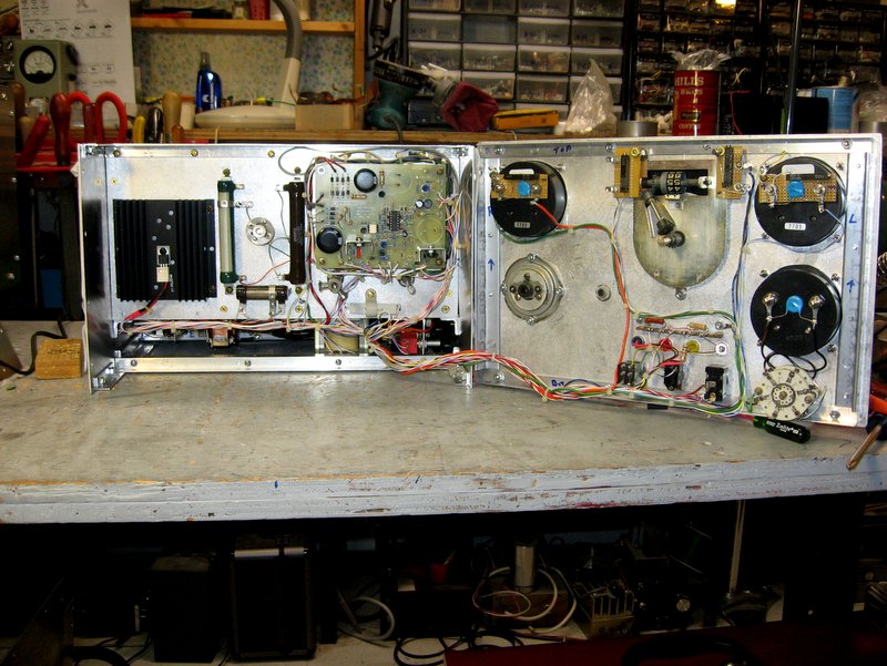
I'm a bit worried about the transformers so close to the tank coils. Now I'm thinking the layout should be entirely different, with the transformers on one side, and shielded from the RF components!  We'll see if this becomes a problem.
Top view
The front panel. I put it together to check that the shafts lined up, etc. I will take it apart to install components between panels and wire it up.

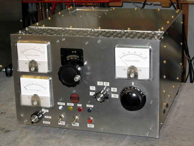
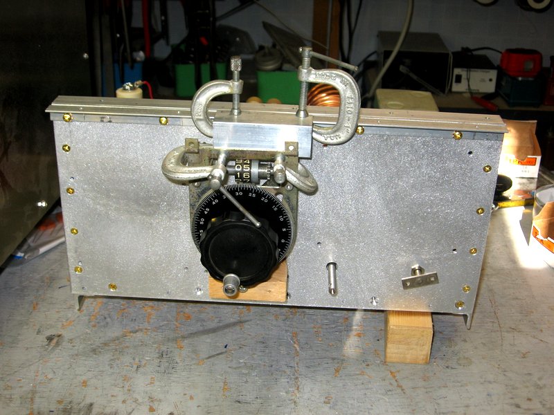
Meter holes were made with a jigsaw. I drilled four 3/8" holes for each meter and connected them up, then cleaned up with a file. I have never found a better way to do this job -- my drill press is much too fast on its slowest speed to use a hole saw properly.

Front panel
Wiring! 

The large heatsink on the left is for the screen regulator MOSFET. Note that the top and bottom of the section between the panels will be perforated metal, so the components will be cooled by convection.

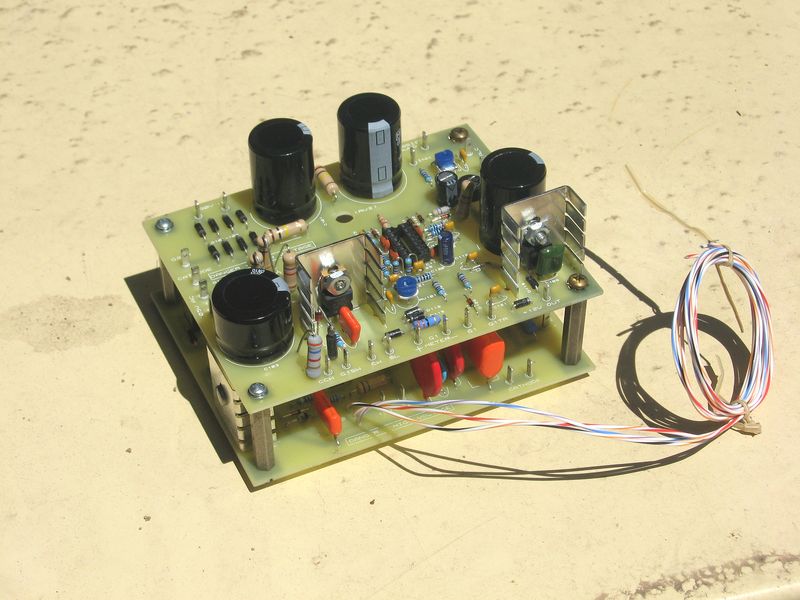
The 'missing' capacitors from the Tetrode Boards stack on the right have been relocated between the boards because some lid failed to pay close enough attention to clearance for the meter.

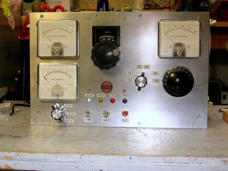
Screen and plate meters can be calibrated with the trimpots mounted on them. The other trimpots on the dial mechanism are for the HV and RF output meters.

The Tetrode Boards have been tested and adjusted. I lost a week by accidentallly switching two wires during testing, and burned out the transformer for the QSK circuit. Lots of dissassembly required to get to it.
Wiring
At last it's beginning to look like an amplifier! There's still plenty to do. Although the bias and screen supplies are checked out, I haven't applied HV yet. I still need to cut holes in the top and bottom covers for airflow. And I plan to add some fans to a "1000 watt" dummy load I have to make it safe for the 1500 watts I expect from this amplifier! Finished front panel
The amplifier showed proper behavior with bias, screen voltage, and HV applied, so it's time to see what happens with a little RF drive. Here I am about to try it with about 12 watts from my K2 (I wasn't quite ready to risk my K3 yet!)

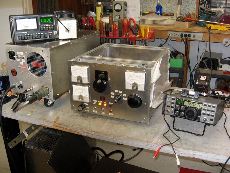
Results were excellent! 12 watts of drive produced more than 750 watts output. I should be able to get full legal power from 25 watts drive.

I still need to cut an exhaust hole in the top cover and fit a silicone rubber chimney to the tube; make a new meter scale for the multimeter (bottom left); and a few other things. Then I will tune it up with full drive on all bands.

You can see the dummy load sitting on top of the power supply near the wattmeter. I added two fans to handle this job!
Test setup
It's finished!

Well, sort of. It is producing in excess of the legal limit on 160 through 10 meters, but there are a few minor changes that I want to make, such as adding a circuit to slow the blower when the amplifier is in standby (and keep it running for a while after transmitting). But I think I will operate it for a while to flush out any problems or weak spots that I don't know about.

This has been a long project, more than two years of sporadic work.  I made a lot of mistakes and had to go back and redo things several times. I might even redo the tank circuit yet again.
Finished amplifier


Back to K2VCO main page