Aligning the PK-232(MBX) for 170 Hz Shift
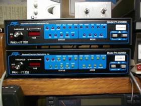
Introduction - The AEA PK-232(MBX)* has been around for several years. It does a very good job on RTTY. There are a lot of better terminal units, there are a lot of worse units, this is one of the most popular units and now that it has been discontinued, they can be had for $100 or less on the used market. Figure 1 shows two variations of the PK-232(MBX). The one on top has only red LED's, while the one below it has both red and yellow. The one on top has a daughter board inside. These units belong to Jim, NØAJ, who has performed the modification described in this article, on the lower unit. He uses that unit for HF AFSK RTTY. The top unit is dedicated to VHF Packet Cluster connection.
What this article describes is; a simple resistor modification that will tighten up the selectivity of the input filters, alignment of the AFSK unit and input filters to 170 Hz shift from the factory settings of 200 Hz. Before you begin, you will need an AC voltmeter or scope. Don't begin the alignment without them.
Resistor Modification for input filters - AEA suggested the following modification to enhance the operation of the input filters for RTTY and AMTOR. As a result, you lose PACKET and ASCII capability on HF ONLY. If you are a serious RTTY operator, I suggest that you make the modification. The result is a controller that hears as good as any of them. What is required is to replace R42,R52,R62 and R72 with 432K 1% 1/4 watt resistors. They suggest that you lift one end of the original resistors and tack solder the new ones in place. The resistors were available from AEA (now Timewave) free of charge by asking for the AMTOR mod. I don't know if Timewave will supply the resistors. The area where the resistors are located on the board is shown in Figure 2. Figure 3 shows where each resistor is located.

Figure 2
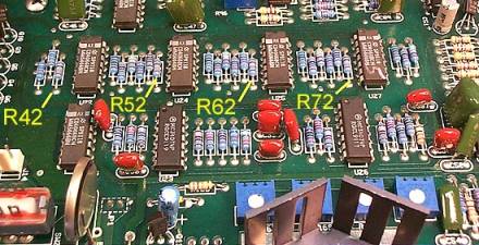
Figure 3
Before you begin, a word of caution about working on electronic devices such as this. You should always wear a wriststat connected to ground and the board should also be grounded. This will minimize the possibility of static build up that could destroy the components on the board. Figure 4 shows how the wristat is employed. The soldering iron should also be grounded.
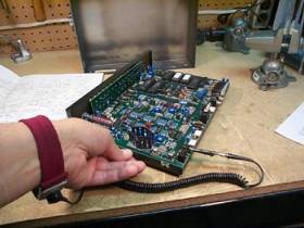
Figure 4
If the 432K 1% resistors are not available from either AEA or Timewave, look in your junkbox, local electronics store, etc. A 432K resistor at 1% tolerance can range from 427,680 ohms to 436,320 ohms, so just try and find a resistor or combination of resistors within that range. I was fortunate to find some 432K 1% 1/4 watt resistors in my junkbox (Military Surplus), that measured 433K according to my digital VOM, Figure 5.
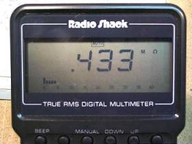
Figure 5
With a low wattage soldering iron, carefully melt the solder on one end of each resistor (the end away from the IC) and lift the resistor out of the solder pad. Bend the resistor lead until the resistor is pointing away from the board. This will give you access to install the replacement resistors. Cut the leads, and solder in the replacement resistors, first one lead into the solder pad hole, and then wrap the other lead around the lead of the original resistor that is still soldered on the board. See Figure 6.
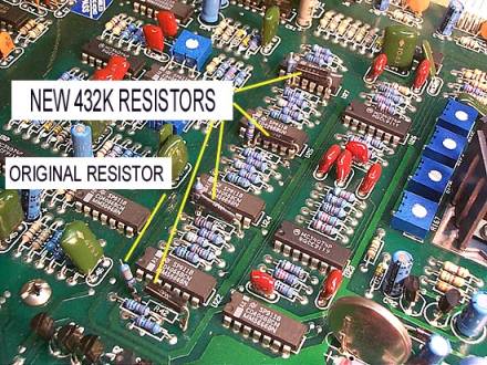
Figure 6
Alignment of the AFSK unit to 170 Hz Shift - The PK-232(MBX) came factory set at 200 Hz shift. This was to accommodate HF Packet. As we all know, HF Packet is dead and except for the W1AW Bulletins, no one is using 110 Baud ASCII. You should adjust the shift to the standard 170 Hz shift used by most RTTY stations. If you use FSK, the shift must be set in your transmitter, but you set the AFSK shift in the PK-232(MBX). Even if you use FSK make this adjustment as we will use the AFSK tones to set some of the filters in the unit. All you do is to bring the controller up using your favorite terminal program in the usual way. Then enter the CALibrate command. The unit will go into the calibrate mode. "H" will toggle the tone generator between wide (1000 Hz) and narrow (200 Hz) shift. You want the narrow shift. The space bar toggles between mark and space tones. When you get the HF space (approximately 2310 Hz), you will see R164 appear just to the right of the tone frequency on your screen. Adjust R164 (Figure 7) until the read-out is 2295 Hz. See Figure 8.
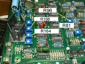
Figure 7

Figure 8
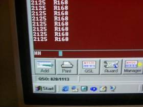
Figure 9
In a similar fashion, adjust the HF mark (approximately 2110 Hz originally) to 2125 Hz (Figure 9). R168 (Figure 7) is used to set the mark frequency. You now have the AFSK set for 2125 Mark, 2295 Space with a center frequency of 2210 Hz. Type "Q" for Quit to leave CAL mode.
Alignment of the PK-232(MBX) input filters to 170 Hz Shift - To align the filters we need to use the output of the AFSK as input. The manual describes a "Loop-Back" mode. The output of the AFSK is fed back into the input by connecting pin 1 to pin 2 of J4 (the flat radio connector). I just used a clip to short pins 1 and 2 together (Figure 10). The connector is labeled pins 5 - 1, not 1 - 5.
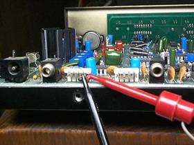
Figure 10
Using your terminal program, bring up the PK-232(MBX). Go into the HF mode by entering the command "VHF OFF". Then enter the CAL command and select the HF mark tone of 2125. Adjust R81 (Figure 7) for maximum AC voltage on pin 3 of J7 or since I didn't have an extra connector, I just put the AC Voltmeters positive probe on resistor R141 to get the voltage.. This is the scope output for the mark signal. Next select the HF space tone of 2295 and adjust R96 (Figure 7) for maximum AC voltage on pin 5 of J7 or on resistor R142 (the scope output for the space signal). When you make these adjustments you can see precisely the LED that lights up with the mark and space tones. You can put a little piece of masking tape just above the LED read-out and mark it with a good black line on each tone. This gives a good reference for precise tuning.
At this point you should have all your ducks in a row, that is, your FSK, AFSK and input filters all on 170 Hz shift with 2125 as the mark and 2295 as the space. This will help you answer on the same frequency that you are receiving.
Acknowledgments - The bases for this article is from the AEA sheet on the AMTOR/RTTY mod and from an article by Jim Jennings, KE5HE, called "The Link" which appeared in the "RTTY Journal, September 1992". I also used the AEA PK-232(MBX) and HAL ST-6 manual. Nothing new here, but is worth repeating. If you have any questions or comments, please send them to me at [email protected].
*PK-232(MBX) means this procedure will work on all models from the earliest PK-232 to the latest PK-232(MBX).