SB-104 LED Digital Display Board

I was faced with an unlit digital display, a dead 180 volt supply, and driver ICs which had been cooked with 13.5 vdc where there should have been 5 vdc. The condition of the gas discharge display tubes was unknown, though I assumed they might be OK. The converter had at least bad transistors and perhaps a bad transformer. I read how the converter was blamed for generating noise in the receiver, and decided to ditch the gas display tubes altogether.
I saw a kit on eBay that totally replaced the display board with a new board that contained the correct drivers for the new LED type 7 segment displays. These auctions kept going for over $100, and was more than I really wanted to put into my $50 radio.
The correct driver for a 7 segment common anode LED is the 74LS47. It turns out that it is pin for pin compatible with the original gas display driver ICs! The only problem being that the replacement LED displays have a much different pin out, and require a dropping resistor in series with each segment. Lets see, 6 displays with 7 segments each yields 42 resistors, plus the one for each decimal point. For me that was a total of 44 resistors.

Above: My reworked LED digital display!
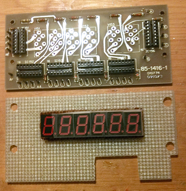
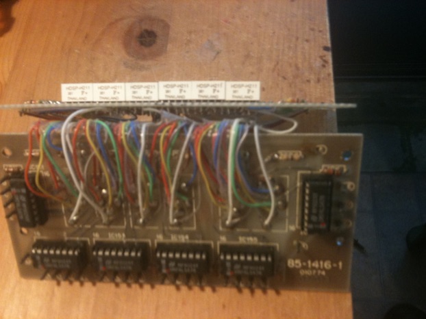
The display board has had its ICs unplugged, and gas discharged tubes removed. Though it has not been done yet in this photo, the resistors across the top of the original display board will all be replaced with zero ohm resistors and connected to the 5 volt supply line. This supplies voltage to the anode commons. Jumper wires could be used in place of the zero ohm resistors if desired. I had resistors, so used them.
A piece of vector board has been cut to the same size as the PC board, and the PC board was used as a drill template to cut the 4 holes, which were enlarged so that the vector board could slide onto the display mounting standoffs. Note the 2 notches, which enable the board to slide past the square switch detents. The new LED displays have been mounted in the desired spot. Note that I slid the displays together. The gap in the original display between the Mhz and Khz digits I found annoying. I lit an extra decimal point to replace the gap. Display spacing is builder’s choice!
Front view of the board showing the dropping resistors for each LED segment. I used 430 ohm resistors because that is what I could get. 470 ohms is the preferred value.
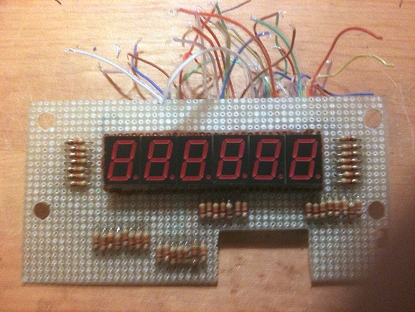
I purchased 3 feet of 10 conductor colored ribbon wire. I only used 9 colors. 7 for each segment, one for the anode common and 1 for the decimal point where I used it. The photo above shows the first digit wired. I used the same color code all the way through, so brown was always the A segment, red was always the B segment, and so on. It looks complicated but it is the same thing over and over again.
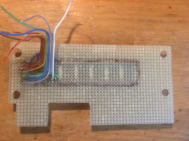
The ribbon wire is all attached to the vector board now. There is actually two layers of wire. The first one attaching one side of the resistors to the display pins, and the second layer attaches to the other end of the resistors, and will be connected to the original display board holes.
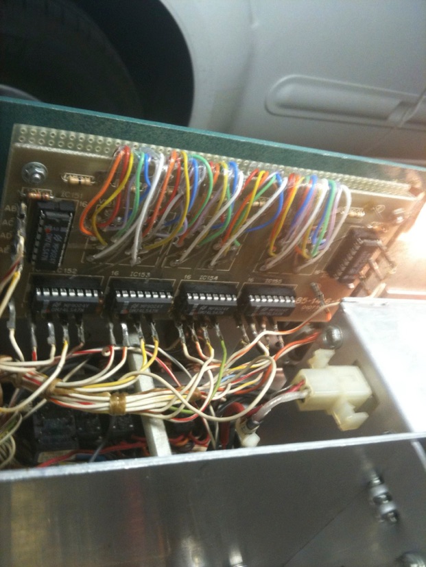
The other end of the ribbon wires, soldered to the holes where the gas display tubes were removed.
Note that the new 74LS47 driver chips have been installed in the original sockets after spraying a little Deoxit on the socket contacts.

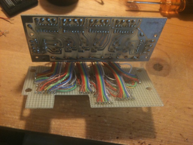
The vector board with the new LED displays easily fits between the original display circuit board and the front panel. All original wiring harness connections are used, with the exception of the 180 Volt connector at the display board top, which is unused. Be careful and do not connect 180 volts anywhere to your new display! I removed my converter box which was not operating anyway. Not only will this prevent accidents but reportedly results in less noise in the receiver once the converter is shut down.
I kept my connections short on the vector board, and there is now a thickness of ribbon cable that prevents the boards from shorting to each other. If desired an insulator of thin cardboard could be used, but I didn’t feel that I needed it. The vector board just hangs on the display PCB standoffs.
Another view of the modified digital display. The cost of the whole display replacement was less than $25.00! Yes, this wiring takes several hours to do, but after all the original transceiver assembly time was something like 80 hours! Work slow, and check your work. I used a small 5 volt supply and checked the wiring of each display to make sure each segment lit when power was applied to the proper color wire. I redid that test once the ribbon cable was soldered to the display PCB, PRIOR to actually plugging in the ICs. It is best to correct any problems before installing the new board assembly into the radio.
Parts required:
6 - HDSP-H211 7 segment, common anode RED LED display .56 inch high
6 - 74LS47N BCD to 7-segment decoder/driver
44 - 470 ohm 1/4 watt resistors
1 piece of vector board the size of the display circuit board
3 feet 10 conductor colored ribbon cable (9 conductors actually used)
The displays were purchased on eBay for $1.39 each, and the 74LS47N was also purchased there. Buy a couple spares of each. You could need a spare at some point, and they will likely be unavailable in the future.
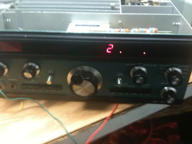
The new display board is lit. This is what you get without a functioning A - frequency counter board installed. The “2” digit is being lit by the bandswitch, and my two decimal points are hard wired.
Though I troubleshot my A board an IC at a time using an oscilloscope, I would have saved time by just replacing every IC and the transistor right from the start. The over voltage condition had blown them all.
HINT: You don’t have to use the TTL version of the ICs. If it calls for a 7490 IC, use a 74LS90 IC if you wish, it is just the low power Schottky version and functions fine. This is true of any of these logic ICs. My A board was repaired with a mixture of of TTL and Schottky ICs, basically whatever I could find at my local surplus house. Two ICs and the 2N2369 transistor had to be purchased on eBay.
Don’t forget the Deoxit on IC socket pins before replacing the ICs.

Frequency counter working but no signal because only A and B boards are plugged into the cage. The “2” is controlled by the bandswitch. It will go out on 80 and 40 meters, will read “1” on 20 meters and WWV, will read “2” on 15 and 10 meters. The remaining numbers are the presets. Numbers preloaded into the counters on the A board. The right 2 digits which now read 3.6 will change depending on the setting of the USB, LSB, CW switch.
PLEASE NOTE: When the boards are on extenders, they may loose their grounding, which takes place between the edge of the card and the card cage guide. The only reason the frequency counter board is working, is that it is picking up its ground from the black cable at the left, the phono connector which is the signal input of the A board. The ground is being picked up from the shield side of the cable. You can also just run a clip lead from the foil at the edge of a board to the card cage chassis, which will insure grounding.
K4ZVG must have been the original owner? No longer in the call database, perhaps a silent key or got a new call. I will put a piece of electrical tape over the back of the call sign to black it out. I do not have the replacement letters to enter K8LBH yet!
At this point, I plugged in the rest of the boards, and the readout on the display is correct. (See photo at top of page.) I hooked up an antenna and now have a working receiver. The performance of the receiver is surprising. It is a very sensitive, good sounding receiver. S Meter works, but transmitter appears to have no output. The adventure continues!