JH5ESM,
Cosy MUTO
16 Sept., 2007
![]()
Connecting large external
antenna to shortwave receiver such as SONY, DEGEN and so on would cause cross modulation and inter modulation.
The first item is a simple attenuator.
Fig.1 shows the schematic of the ATT. Two diodes are for protecting RF section of the receiver. 1N4007 may be useful for static protection.
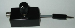
Whole the attenuator has been implemented into a small ABS enclosure. The dimensions are 30[mm]W, 50[mm]D and 20[mm]H. There are two input terminals: one is an RCA pin jack, and the other is 3.5[mm] monaural jack. Output cable is 1.5D-2V with 3.5[mm] monaural plug.
 |
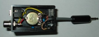 |
| (a) overall view | (b) inside view |
DEGEN DE1103 can be used as a mother receiver for ham transmitters because it has enough sensitivity and frequency stability. However, its selectivity is not sufficient for CW operation because IF bandwidth is too wide (4[kHz] in narrow mode).
 |
 |
| (a) Schematic | (b) SPICE simulation results |
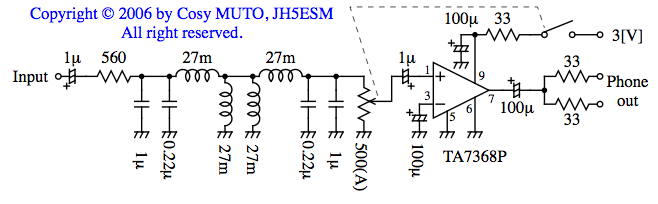
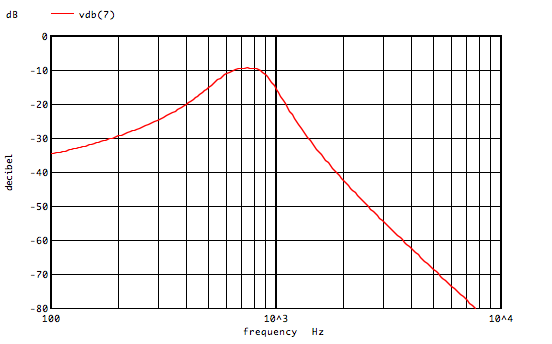
Fig.3 shows the schematic of the audio filter and expected frequency response (click figures to enlarge).
Audio signals from phone jack (not the "LINE OUT") are led into 560[Ω] termination resister.
The filter is 3rd4th order m-coupled BPF of 750[Hz] center frequency and 330[Hz] -3[dB] bandwidth (Approx. 500[Hz] BW for -6[dB] bandwidth). Filter inductors are of low resistance as possible and should be magnetic shielded. Otherwise, the filter would not work properly. Capacitors should be film type.
TA7368P boosts filtered audio signals to drive external speaker or phones.
The entire filter unit including two AA cells is implemented into a
W100×D70×H30[mm] aluminum enclosure as shown in Fig.4.
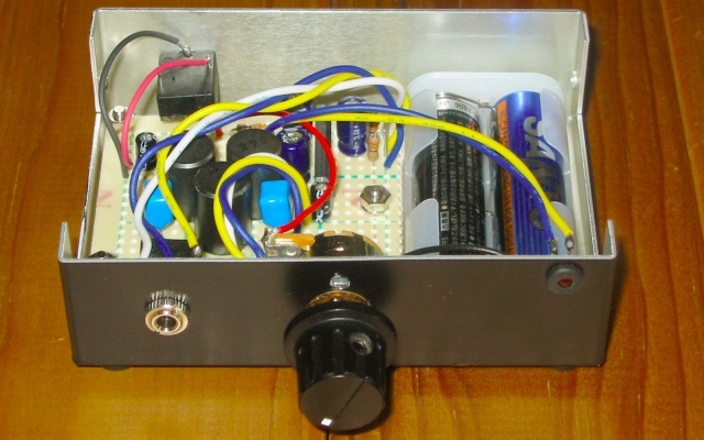
Fig.4 The BPF unit.
![]()
![]()