 |
|
| ponte a rumore // noise - bridge |
| by Nino Paglialonga_1988 |
|
| Utile apparecchio per la misura di antenne e linee
abbinabile ad un qualsiasi ricevitore. Individua la
frequenza di risonanza o se è corta o lunga per una data
frequenza misurandone l'impedenza.banda utile = 3.5-30
mhz R = 0 - 200 ohm _X = reattanza (vedi testo )
precisione +/-5% _Alim.= 9v / 6ma _misure accurate =
circuito ausiliario per discriminare il nullo dal rumore di
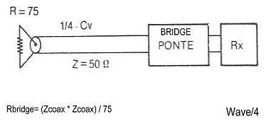
fondo dell'Rx frequenza d 'uso. Misura d' antenna :
collegare il ponte all'Rx e su Zx connettere direttamente
l'antenna tramite cavo lungo mezz'onda.Tenere presente
il coefficiente di velocità (Cv ) che per i cavi in polietilene
compatto è 0,66,mentre 0,81 per quello spugnoso.
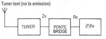
Lambda /2= (300000/FMhz)/2 moltiplicato per " cv " | Useful instrument for antenna testing and measurements
as well as for cutting precise lambda/4 or lambda / 2
stubs. Its output goes to a Receiver tuned on wanted
frequency.Range: 3.5/30 mhz , R: 0 / 200 ohm , X = see
text,good precision +/- 5% , pwr 9vcc/6ma Accurate null
findings due to a simple but effective aux circuit for
discriminating null noise from Rx floor noise. Antenna
measurement : insert the bridge directly onto the
antenna or using a coax cable having a wave/2
lenght.Take into account the Cv (velocity coefficient)
usually 0,66 for compact dielectric and 0,82 for foam
type. Lambda /2= ( 300000 / FMhz ) / 2 then multiply by
" cv ". |
 |
| foto prototipo dopo 15 anni d'uso | prototype-picture after 15 years of use |
|
| esempi grafici _______________ graphic examples |
 |  |
| Taratura: verificare che a 3,5 mhz sull'Rx il soffio sia
robusto (S-9 ), eventualmente regolare il trimmer in serie
allo zener. Misurare il potenziometro (tipo lineare) ogni 5
o 10 ohm ed annotarne i valori e relativa indicazione
della manopola su carta millimetrata .Collegare una
resistenza antiinduttiva (es. 50 o 100 ohm) con terminali
cortissimi e variare R e X per il miglior nullo possibile.
Annotare la posizione della manopola del variabile
"X",questo punto sarà lo zero. Se si dispone di
capacimetro misurare la capacità a variabile staccato e
segnare la capacita' ogni 10pF sopra e sotto lo zero . | Alignment:the noise signal is robust, at least s-9 if not
(too weak or too strong)adjust the trimmer on the zener
diode.Take note of the knob dial and potentiometer
value (readings every 5 or 10 ohms and noise bridge
off).Connect a 50 ohm non inductive (carbon) resistor on
the Zx input with extremely short wires. Switch-on the
bridge and rx-power on 3,5mhz and rotate back and forth
the "R" and "X" knobs for the best null . The " X "
position of the knob will be the "zero" reference ( X =0 )
of your bridge.Know you can measure the capacitor
every 10 pf from this point (plus or minus). |
 |  |
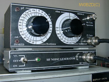 |
| bel prototipo realizzato da Pino_iw0bzd : si noti la particolare
accuratezza di esecuzione ...dentro e fuori il contenitore | Pino_iw0bzd _fine "professional" prototype : high accuracy is a must
. . . outside and inside the enclosure |
|
| Altrimenti, il nullo annotato sarà il riferimento per la
misura della antenna alla risonanza (X = 0) . A ponte
spento e senza staccarla misurare la resistenza con
l'ohmetro, i valori misurati col nullo e con l'ohmetro
devono avere uno scarto NON superiore al +/- 5 %.
Ripetere la misura a 30 mhz ,se lo scostamento di X non
è contenuto ,controllare la simmetria delle connessioni,
fili del trasformatore uguali e max lunghezza 2 cm,
spostare eventualmente il terminale libero su altra
direzione , verificare che le masse siano corte .Il
prototipo non ha dato problemi. La capacità fissa sul
ponte è pari alla metà del condensatore variabile_ | If you haven't a cap. meter don't worry, this position x =
0 will be your marker for a resonant antenna.Check
effective ohmic values and reading values ( within 5%)
and repeat these operations on 30MHz (R test and X = 0
) . " X " must be very close to zero reference found on
3,5 mhz.If not, pay attention to the stray capacitances
,wire lenght and symmetry of components layout.The n.
c. arm of the transformer can be moved onto other
directions. Differencies of R readings must be within 5
%. For accurate readings or hard to find nulls, insert the
pulse modulator. |
 |  |
| suggerimenti: schermare la piastrina rispetto al ponte,la
piastrina non deve essere collegata a massa sulla scatola
(metallica),ma tramite cavetto schermato deve
attraversare lo schermo (senza connessione) e collegarsi
a massa in punto comune ove convergono tutte le
connessioni del ponte e dei connettori ingresso/uscita. Il
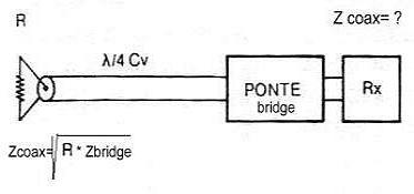
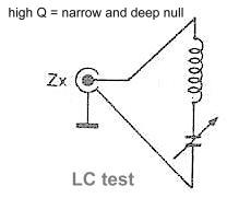
potenziometro "R" va demoltiplicato. Alcuni tipi non
raggiungono lo zero,in tal caso per misure accurate su
fattore di velocità o per dimensionare cavi a mezz'onda o
quarti d'onda ricorrere alla misura alternativa (vedi
testo). TLC555 = NE555 versione c-mos a basso
consumo. | Hints: the board must be shielded but not be
grounded.The board output signal cable must pass
through a hole in the shield and ground (cable shield)
connected directly to a common grounding point ( board
and bridge). A big knob must be used for "R". Some
potentiometers doesn't reach "zero", therefore for
accurate lambda/4 and lambda/2 cable measurements or
for "CV (cable velocity factor )" testing see notes in the
text. TLC555 (c-mos version for low-power) = NE555
|
 |  |
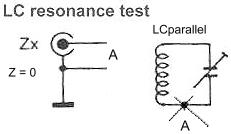
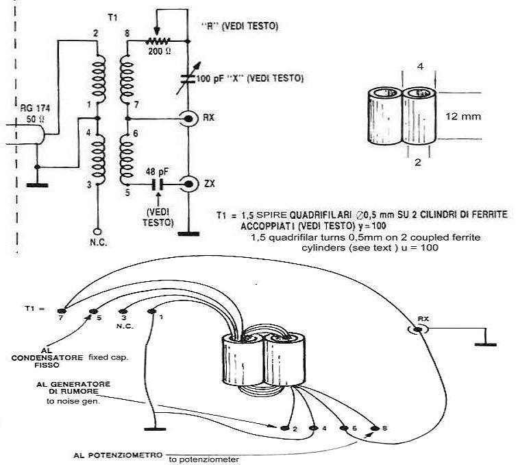
| ADDENDA : per speciali antenne non risonanti o per
particolari stub od altri usi possono essere usate le
seguenti formule : A,B,C. ( A ) _ Xc = (159155/48-C)-3316
( B ) _ XL = 3316-(159155/48+C)
( C ) _ X = Xc (or XL)/ fMHz
Xc e XL riferite a 1 MHz .
Il valore zero di X corrisponde a c = 48pf (capacità del
ponte )- "3316" è la reattanza calcolata ad 1 MHz di C =
48pF .
| ADDENDA : for special ( non resonant ) antennas or
particular stubs or other uses may be applied the
following A,B,C, formulas. ( A ) _ Xc = (159155/48-C)-3316
( B ) _ XL = 3316-(159155/48+C)
( C ) _ X = Xc (or XL)/ fMHz
Xc and XL are referred to 1 MHz.
Zero value for X is equivalent to C = 48pf ( bridge
capacitance ) _"3316" is the 48pF reactance calculated
at 1 MHz.
|
 |  |
|
 |
|
 |
 |  miscellaneous miscellaneous |