LC METER
Inductance
and Capacitance meter
using
"Frequency Shifted Oscillator"
The most
mysterious components for radio-amateur (I suppose) are inductors;
infact you can measure all other (resistor capacitor) with a simple multimeter
but not an inductor;
So you must:
1) pay a lot of money for a professional LC meter;
2) use other indirect, uncomfortable way;
3) go fishing HI.
I've tried 3) and 2), then I've decided to home-made one.
I've built various L(C) meter; the following is one of best system but some more
calculations are needed (who is the only disadvantage, so I've written a Visual
Basic software to simplify operation).
It measure both inductance and capacitance (1-NanoHenry - 100 milliHenry for
inductors and 1pF - 500nF for capacitor) and accuracy (who depends by
calibration's component) is exellent,
but don't forget you're using a free oscillator, so frequency drift and
inaccuracy at low value (1-10 nH, 1-10 pF) are to be expected;
With a lot of care in calibration, you can have exellent results.
Here follows a simple test where I compare LCMeter with my commercial
Capacitance meter:
| Marked value | Commercial C-meter | LC Meter |
| 10 pF | 9,8 | 9,6 |
| 15 pF | 14,9 | 14,6 |
| 100 Pf | 99 | 99,6 |
| 2,2 nF | 2,22 | 2,22 |
| 10 nF | 9,96 | 10,11 |
| 100 nF | 101 | 100,3 |
Regardig inductor, I can not make the same test because I have not a commercial L-Meter or well know inductor, but the same results are to be exected.
When I made the LC meter the first time, I've built it only as inductance meter;
that was because I already have a commercial Capacitance meter and wanted avoid stray
inductance-capactance due to switch, more cable etc, but there wasn't big differences
so I've added back the C-meter.
The project is well know on the net because selled by AADE;
it works around
a "frequency shifted oscillator"
who is well described in "RF Components and Circuit" by
RSGB;
Click here for electric schematic
Let's
see schematic;
A LM311 oscillate at frequency F1 (determinated by L1 and C1, around 650 Khz);
There are 2 possible operating mode:
1) CX mode, where the unknow component is placed in parallel to L1 and C1 (and allows measuring both Inductance and capacitance) and
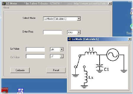
2) LX
mode, who allows measuring only inductance placed in series with L1;
CX MODE
Placing C2 in parallel with L1 and C1 cause the LM311 to oscillate at a
lower frequency, F2 (the total capacitance is now C1+C2);
If we
know F1, F2, L1 e C1 we can calculate C2 with a simple formula:
F1 ed F2
are well know (we use a frequency-counter to measure it), L1 and C1
are know only after calibrating the LC meter (wich is needed only once and is
very easy to do).
We put a well know capacitor in parallel with C1 ;
frequency F1 will change in F2 (lower);

F in
Hertz - L in Henry - C in Farad
or
F in Khz - L in mH - C in mF
or
F in Mhz - L in uH - C in uF
solving
the above equations we obtain C1 and L1 value, (stray inductance and capacitance
are included);
now we know all we need, let's insert an unknow capacitor in parallel with L1,C1 ,measure
the new frequency (F2) and calculate Cx :

F
in Hertz - L in Henry - C in Farad
or
F in Khz - L in mH - C in mF
or
F in Mhz - L in uH - C in uF
It's also possible measuring unknow inductance in CX mode; let's insert Lx in parallel to L1, C1.

Calibration is the same as above (you don't need to re-make it), so just insert Lx, measure F2 and calculate Lx using the below formula:
F in
Hertz - L in Henry - C in Farad
or
F in Khz - L in mH - C in mF
or
F in Mhz - L in uH - C in uF
LX MODE
Using an inductor (L2) in
series with L1 cause the frequency to oscillate at F2 (lower than F1) (when
in series L total=L1+L2);

Knowing F1, F2, L1 e C1 it's possible calculate the unknow L2 with simple
math formulas.
Infact F1 and F2 are well know, L1 and C1 are know only after calibrating the LC
Meter, calibration who is very similar to CX mode but using different
equations.
To calibrate the meter insert a well known inductor (L2) in series with L1;
F1 will change (down) to the new frequency F2;

F in
Hertz - L in Henry - C in Farad
or
F in Khz - L in mH - C in mF
or
F in Mhz - L in uH - C in uF
Solving equations we obtain C1 and L1 value, containing stray inductance
and capacitance;
At this
point we know all, just insert an unknow inductor (Lx), measure the new
frequency (F2) and calculate Lx as below:
F in
Hertz - L in Henry - C in Farad
or
F in Khz - L in mH - C in mF
or
F in Mhz - L in uH - C in uF
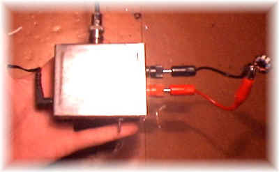
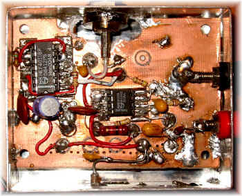
CONSTRUCTION
I've used a small metallic box (8x6x3 cm), a bnc for connecting the
frequency-counter, a power supply jack, a 2-way switch and test leads;
A 1 Mhz
frequency meter and calculator is needed ;
To avoid spending a lot of time in calculation I've written a Visual Basic
software who make all calculation pressing a key;
Click here to download LCMeter.exe
USING LC
METER
Switch-on LC Meter and wait few minutes;
read the oscillating frequency (F1);
Calibrate it (CX mode calibration is better because you can easy-find
precise value capacitor, but you can calibrate it also in Lx mode using a well
know inductor - anyway, however you calibrate it, results are ok for all mode)
and read the new frequency (F2);
Insert F1, F2 C2 (or L2) in the software (or use the above formulas) to
calculate L1 and C1 (the tank circuit);
LC meter is now ready, just select the operating mode (LX o CX), insert unknow
component and write F2 (the new frequency) in the software:
press F1 (or calculate button) and the calculated value will be shown on the
screen.
If switching from Cx to Lx mode (in that case short-cut test leads) you read a
different frequency (F1) don't worry, that's not a problem and is due to small
stray inductance - capacitance; but that differences must be very small (i.e.:
if i try to calculate Lx value short-cutting test leads with a very short wire,
i obtain -4 / -11 nH);
If not so, re-wire the circuit using as short as possible cable (expecially
in the LC circuit).
Take
wire as short as possible and calibrate LC meter more time during operations;
If accuracy measures are needed, don't use external test leads;
anyway using my software you can zeroing LC meter (only in LX mode, with the
"Stray Inductance" textbox);
Just calibrate the meter (with no external test leads), switch to LX mode,
insert and short-cut external test leads, calculate stray inductance and insert
that value (in NanoHenry) in the "Stray Inductance" text box;
the software automatically will subtract that value in following measurements;
I've written some source code for a 16F84 PIC microcontroller to automatize all, but I've never finished it; I'll be happy to see that work finished.
P.S. in
schematics I've added a LM7808 but you can use also 12V DC.
Click here for electric schematic
Click here to download LCMeter.exe
73 de iz7ath, Talino Tribuzio