SIGNAL TRACER
Signal tracer is a simple audio
amplifier with high impedance input used to "hear" a signal in a circuit; ther's
a probe (with a switch for "Radio freq." or "Audio Freq.") to insert
in the circuit;
signal on the probe is amplified by the audio amplifier IC and then you can monitor and
hear it in the speaker or in earphones. It's very easy to build but at the same time it's
very useful: if you have a broken receiver, just put an rf signal in the antenna, put the
probe (RF switch) after the first rf amplifier in the receiver: if all is working fine
you'll hear the signal (that you have injected in the antenna, rectified by the probe),
otherwise you have found the problem; if you hear the signal go head in this way until you
stop hearing it: there is the problem. The last thing to check is the speaker (remember to
switch the probe in "Audio freq").
I have found this signal tracer very useful in my shack: to "hear" if an audio
pre-amplifier is working or not, to test some microphonic capsule, to test modem, audio
filter; but there are many other applicationes: you can use it as an external speaker for
walkman and small portable tape-recorde, as oscillofone for your cw key (with a small
audio generator) and so on.
I found this project on an italian magazine (RadioKit 1/94 pag 43).
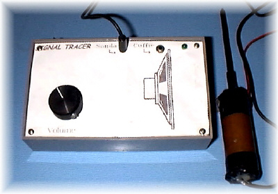
There are few components: at first a fet amplifies signal coming from probe without
loading the circuit under test; then an audio IC (TDA2006) amplifies the signal so that it
can be heard in a speaker on harphones. On the front side of the box there's a jack for
probe and earphones; in the rear ther's a 12V DC jack (See Picture 1); the board take place in a shield box (if
you have not one, use a plastic box shield with a tin foil).
73 de iz7ath, Talino