HOW TO USE A CB AMPL. ON HF BANDS
In this page I'll explain you how
to build an HF-linear amplifier using an old CB one.
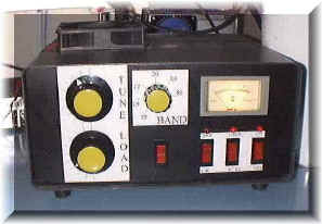
Some time ago Antonio (ik7ytx), told me he had an old-broken CB linear amplifier in the
cellar with 3xEL509 (BV603, See
Picture 1); he asked me if was possible to use it on HF bands: "sure"- I
answered - "but it will give you no more than 250-350 watt!" (depends on some
factor).
He was agree so.....let's start!
You can make the same with all CB amplifiers
using 2-4-5 EL509 - EL519 - 6KG6 or similar; it's easy, you don't need particular
knowledge! At first disassemble the amplifier: the most important part is the transformer;
it have one primary (220 v) and two secondaries: 800V for plates and 6,3V/6A for heaters;
originally one tube was used as driver for the last two (CB RTX gives usually 5-10 w) but
I used the 3 tubes in parallel (ham RTX gives 100 w..); the circuit uses 3xEL519 in
grounded grid configuration;
have a care to put all parts tidily in the box:
1) Tubes and its printed board;
2) transformer and power supply;
3) Pi-greek and switches;
put them (i.e.) left to right (RF in - Amplifier - RF OUT ecc.) and take wires as short as
possible.
First printed board is H.V. power supply (See Picture 2): I re-used original parts; there is a full
wave bridge (4xBY255) as rectifier circuit, than a ripple filter made with a series of 3
electrolytic capacitors (150 microF.- 350 VL); a voltage equalizer resistor (390 ohm) is
connected across each capacitor; at the end we have a fuse and a 30 ohm resistor.
Input voltage is 700-800 V AC and output is 960 V DC (unloaded, about 700 loaded; I put
the board on the same transformer.
Heaters use A.C. directly from transformer, so no circuit is needed.
About biasing, I didn't build any board; there is not a secondary transformer for negative voltage: grids are grounded and there's a resistor between cathode and ground that make grids negative respect to the cathode (that means cathode is positive respect to the grids: in tubes all voltages are infact reported to the cathode). With a transistor (BD246C) and two zener you can select the right bias for SSB or CW; we have only few components (see Picture 3).
If in your transformer there is not a secondary for relays, light ecc, you can doubler heaters voltage or simply use an other small one: I use a toroidal transformer (See Picture 4).
How I said, tubes are in grounded grid
configuration; RF signal come in from cathodes trough a capacitor and a 3,4 Ohm resistor
(you can by-pass the resistor, if you have not enough power) and go out to the plate,
where there's a capacitor which prevents High Voltage going to antenna and than the
Pi-Greek circuit; high voltage comes to the plate trough an RFC (anode H.V. RF chokes); I
bulit it using transformer-copper wire (diameter 0,4 mm, 10 mt length) on an insulated
support (I think mine is a fiberglass-mix, 25 mm diam.); to avoid self resonance situation
(which can destroy the choikes) make the Inductor not continuous; two relays
(INput-OUTput) provides for switches.
All these components are mounted on a printed board (See
Picture 5).
All RTX today have a PTT jack for an external
Linear Amplifier, anyway I put a vox circuit on this amplifier which is used everytime Ptt
jack is not present; a RF signal is drawn with a probe (a small resistor plus a
capacitor), rectified with an 1N4148 diode and applied to the base of a transistor;
I used two relays 12V-coil/10 A contacts (two way-two switches) (See Picture 6).
You need two varable capacitores (one
2-3000V/150-350 PF, the other 1000V/600-1000 PF), some mica-capacitores for low band
tuning, one inductor and a switcher (See Picture 7); .
Take a care for the plate-capacitor: it should have a very low minimum-capacitance; on 28
mhz you need few Picofarad for a good "Q", because the capacitance (for the 3
EL-519) is very high; a good way is not use C1 on 28 mhz, but you need one more switch! My
amplifier, infact, doesn't perform 100 % on 28 Mhz. About band coverage, these are:
10,15,17,20,40 e 80 meter (but you can add more).
COMMENT
The amplifier is now in IK7YTX's shack and,
although I used old-used tubes (they comes from an other amplifier), it works fine!
Remember to use a fun!
Original
Electric Diagram
New Electric Diagram
Vox and Switches Electric Diagram
Componentes
Printed Board
73 de iz7ath