Hi, i am Mauro Dainese, born in 1946, first licensed in 1964 in Rome as I1KGR later changed to I0KGR with adoption of call areas in Italy.
Ph.D. in Electronic Engineering at Rome University in 1971, began my job in cement plant industrial sector, so for a certain time i had to leave
Amateur Radio hobby well apart. Went back after some years with new callsign IK0CAK. Moved some 25 years ago to East Coast of central Italy as IK6CAK.

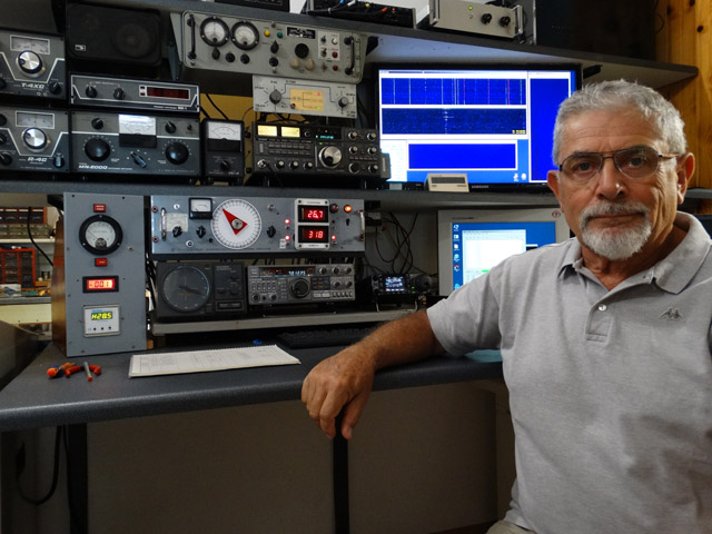
Always more interested in design and construction of my own rig than in operation and Award collection, in the last two years, also in connection with
retirement from main job of my engineerig office, began to work around EME.
Living in a quiet semi rural location (also really very good for HF) on a hill not far from Adriatic sea, had an intense brainstorming trying to configure
my antenna system in connection with backyard conformation, threes, in the meanwihle wildly grown in the garden, and fierce opposition of the XYL against
any offence to them. An other issue was the possibility to work at antennas for erection and maintenance without cranes and in safe conditions.
That means no chance to use long Yagis.
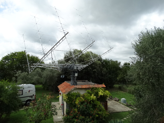
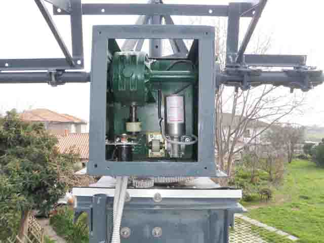
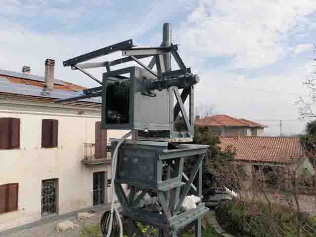
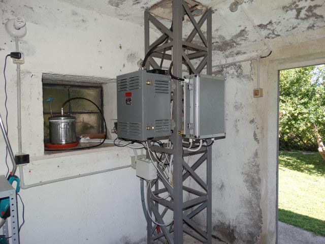
I revamped a sturdy tower with heavy rotating head and elevation box made some 30 years ago for a 3 m dish based on industrial gear boxes and placed it on
the terrace of a small storage building in the garden. The whole arrangement is not high at all, not a big problem for EME, but has an excellent
accessibility.
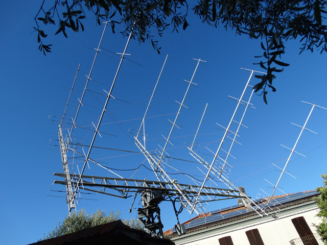
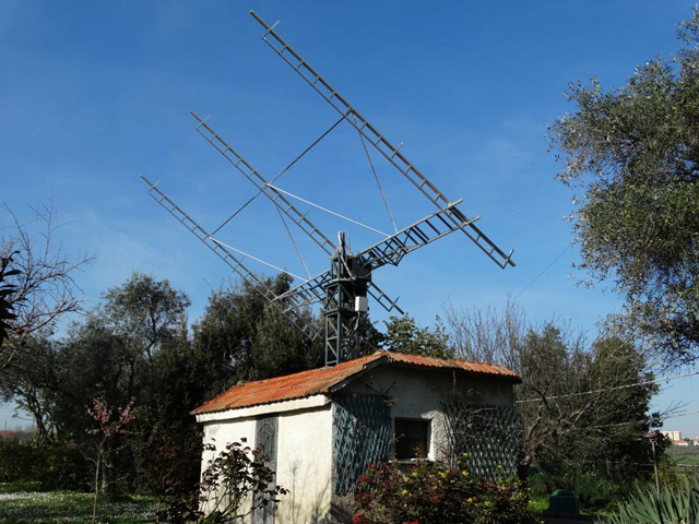
The (forced) solution was an hybrid between the old way of a courtain of many short antennas and the usual 4 long Yagi configuration, that means an array of 9
hanging Yagis back supported, therefore, as positive issue, without any obstruction in the front side.
The problem was to build a supporting structure connected to the two shaft ends of the elevation gear capable to hold weight and wind load of the nine 2-wavelengts
crossed Yagis 3,15 m apart horizontally and 2.4 m vertically so an array abt. 6.3 m wide and 5 m high.
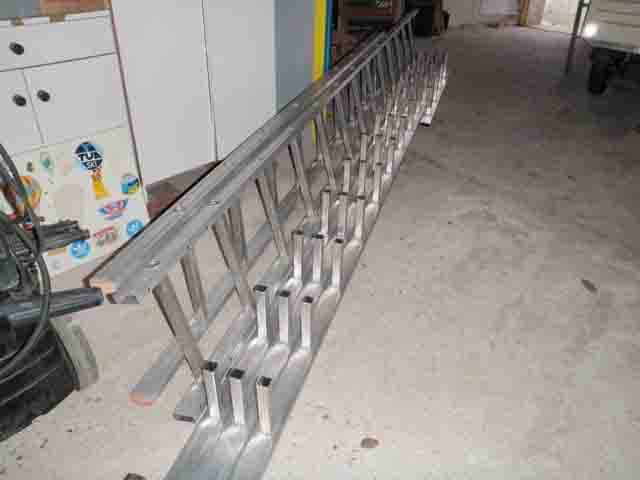
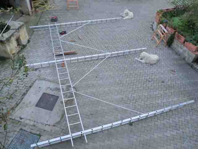
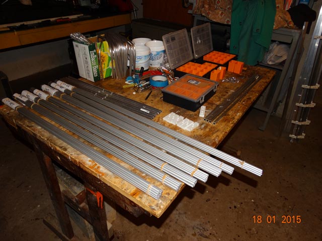
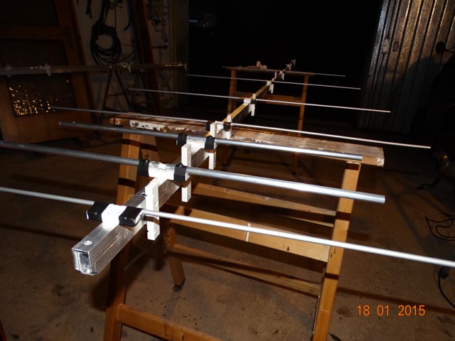
The idea went looking at ladders at hardware/garden shops. Why not using good quality aluminium construction ladders as main horizontal beam (building with some
steel understructure a sort of lattice). For vertical supports i cut longitudinally the ladders connecting then the remaining half steps with aluminium angle profiles.
The nacked structure can be seen in the picture. At the top i have only horizontal antennas to reduce the wind load, so 9 H 6 V.
The whole survived safely to a wind storm with gust of more than 60 knots.....hope will continue.
The number of coupled Yagis can seem very ODD. Firstly ist the way to pack at a quite reasonably spacing antennas enough to cover with capture surface the real
occupied area. The vertical spacing is rounded to meet the step spacing of the ladders.
The coupling of nine 50 Ohm loads is not a problem. If you connect togheter tree 50 Ohm antennas with an equal lenght of 50 Ohm cable you find at the connection an
impedance of 16.66 Ohm. You have tree such sets. The source impedance (PA out/LNA in) should be 50 Ohm. Tree sets of antennas in parallel should show each 150 Ohm
to give 50 Ohm. If you calculate the caracteristic impedance needed for a coupling line (odd quarter wavelengt) to transform 16.66 Ohm to 150 Ohm : surprise ! it's 50 Ohm !
So everything is made with 50 Ohm cable, each of tree sets with soldered joints, no connectors. Of course every H1000 cable lenght was trimmed with aid of noise generator
and spectrum analyzer, althougt once the harness is connected toghther it is difficult to understand how good can be up to the moment to have everything up.
SWR is outstanding !(of course provided all antennas are correctly tuned)
For the six vertical antennas is something else, instead of coupling 3 sets of two or 2 sets of tree, i tried a direct approach coupling all six togheter :
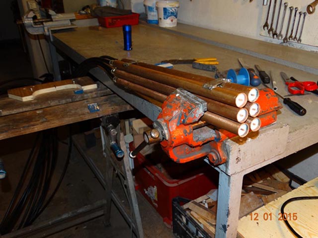
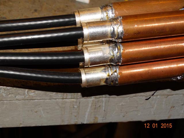
The inner conductor of the six cables coming from each antenna (2.62 mm dia) continues as inner conductor in a 20 mm inner dia. copper tubing quarterwaveleght
The caracteristic impedance of abt. 120 Ohm transforms the 50 Ohm of each antenna into 300 Ohm. Six in parallel gives 50 Ohm ! Some plumbing work, but SWR 1:1
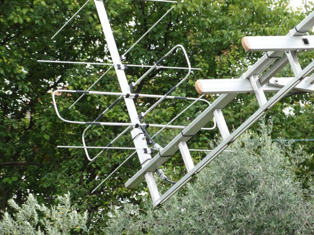
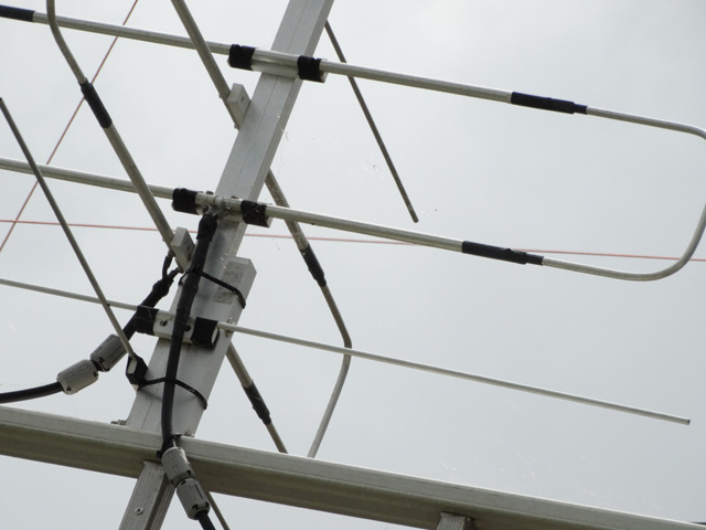
 About antennas : here the choice was as usual to do all in my own. The available dimensioning out of simulation was the outstanding work of Justin, G0KSC.
Looked several solutions out of the LFA, built a test one, really a 11LFA+2, still in use on another tower, and finally, also on the base of available material, choosed the
8LFA project, Tanks Justin.
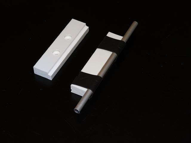
For the connection of the elements to the boom tried an original solution: the insulators are cut out of PVC bars fixed to the rectangular boom with self tapping stainless steel
screws. One edge of the insulator is easely machined to give seat to the element (6 mm dia. tubing), the element is glued along the insulator (Bostik PolyMax) and wrapped on both
sides with high quality termoshrinking tubing while glue still soft.
About antennas : here the choice was as usual to do all in my own. The available dimensioning out of simulation was the outstanding work of Justin, G0KSC.
Looked several solutions out of the LFA, built a test one, really a 11LFA+2, still in use on another tower, and finally, also on the base of available material, choosed the
8LFA project, Tanks Justin.
For the connection of the elements to the boom tried an original solution: the insulators are cut out of PVC bars fixed to the rectangular boom with self tapping stainless steel
screws. One edge of the insulator is easely machined to give seat to the element (6 mm dia. tubing), the element is glued along the insulator (Bostik PolyMax) and wrapped on both
sides with high quality termoshrinking tubing while glue still soft.
 I did not made up to now a very accurate plot of the array (need a stable beacon and have some reflections to take into account being the antenna very low on ground at 0� elev),
but estimated 15-18� at -3dB. First deep null at 13� each side on azimuth. F/B at least 28 dB. In fact seems to work very well aimed to the fickle moon and do not collect too
much noise from the backside. No Baluns.....to simplify the cabling (15 antennas)...instead lot of ferrite beads...seems good enough.
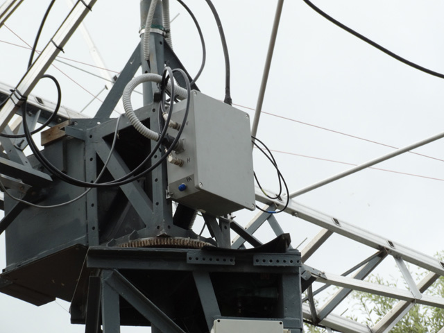
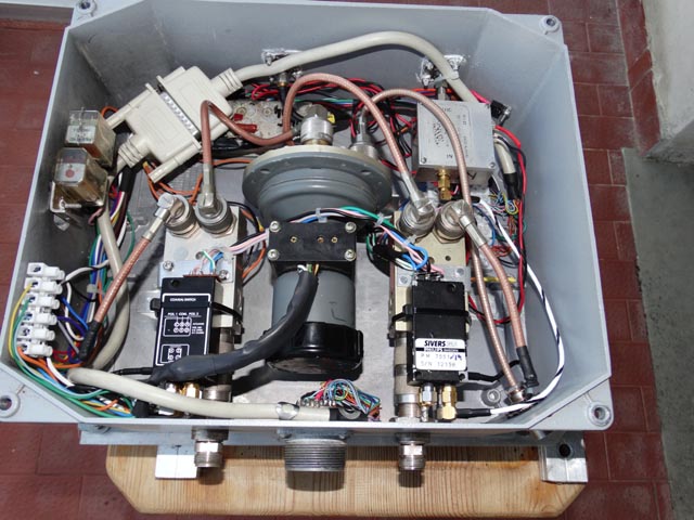
The two arrays converge in a box with two T/R coax relays(N connector). On transmission they connect antennas to a Jennings vacuum relay choosing either horizontal or vertical to
Power Amplifier (5 m for now RG14 with C connectors). On receive H and V into two separate ways : to further safety latch protection relays (SMA), two LNAs, RG58 C/U lines down
in the building, two line amplifier (abt. 20 dB) then abt. 35m RG58 C/U to shack in a buried PE pipe togheter with all other cables.
All command and measure connections are strictly analogic as well as no switching power supplies or network devices in the vicinity of the antenna to avoid lethal birdies !
I did not made up to now a very accurate plot of the array (need a stable beacon and have some reflections to take into account being the antenna very low on ground at 0� elev),
but estimated 15-18� at -3dB. First deep null at 13� each side on azimuth. F/B at least 28 dB. In fact seems to work very well aimed to the fickle moon and do not collect too
much noise from the backside. No Baluns.....to simplify the cabling (15 antennas)...instead lot of ferrite beads...seems good enough.
The two arrays converge in a box with two T/R coax relays(N connector). On transmission they connect antennas to a Jennings vacuum relay choosing either horizontal or vertical to
Power Amplifier (5 m for now RG14 with C connectors). On receive H and V into two separate ways : to further safety latch protection relays (SMA), two LNAs, RG58 C/U lines down
in the building, two line amplifier (abt. 20 dB) then abt. 35m RG58 C/U to shack in a buried PE pipe togheter with all other cables.
All command and measure connections are strictly analogic as well as no switching power supplies or network devices in the vicinity of the antenna to avoid lethal birdies !
 I had to work a bit to find the correct gain distribution and the correct LNA configuration to avoid instabilities, excess gain, immunity from in band signals (especially from digital
communication bursts) but this is what we like.
I began receiving with two LNAs and a FCDPP switching remotely the antennas at LNA box to have H, V, as well as slant and circular polarization....worked well but i liked to have dual
IQ reception.
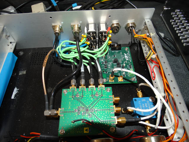
The well known IQ+ was a solution, but again i liked to make something myself. I bougth two ADL5387 evaluation boards from Analog Devices as well as a Si570 evaluation board from
Silicon Labs and assembled my IQ direct conversion receiver. (No means to attempt to use those microscopic chips as they are without printed circuit and special soldering techniques !)
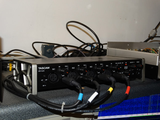
The ADL5387 boards comes with wired unbalanced baseband outputs (2 boards - 4 outputs). It was rather difficult the connection with PC 4 channel audio board (hum, birdies....software
instability) At last purchased a rather inexpensive TASCAM US-4x4 external audio interface (kind used by DJs) and made on ADL Board a rather delicate wiring modification, altought foreseen
by Analog Devices, to have balanced outputs meeting the balanced inputs of the audio interface. As result a very clean picture on MAP65 without any birdies coming from inside the station.
I had to work a bit to find the correct gain distribution and the correct LNA configuration to avoid instabilities, excess gain, immunity from in band signals (especially from digital
communication bursts) but this is what we like.
I began receiving with two LNAs and a FCDPP switching remotely the antennas at LNA box to have H, V, as well as slant and circular polarization....worked well but i liked to have dual
IQ reception.
The well known IQ+ was a solution, but again i liked to make something myself. I bougth two ADL5387 evaluation boards from Analog Devices as well as a Si570 evaluation board from
Silicon Labs and assembled my IQ direct conversion receiver. (No means to attempt to use those microscopic chips as they are without printed circuit and special soldering techniques !)
The ADL5387 boards comes with wired unbalanced baseband outputs (2 boards - 4 outputs). It was rather difficult the connection with PC 4 channel audio board (hum, birdies....software
instability) At last purchased a rather inexpensive TASCAM US-4x4 external audio interface (kind used by DJs) and made on ADL Board a rather delicate wiring modification, altought foreseen
by Analog Devices, to have balanced outputs meeting the balanced inputs of the audio interface. As result a very clean picture on MAP65 without any birdies coming from inside the station.
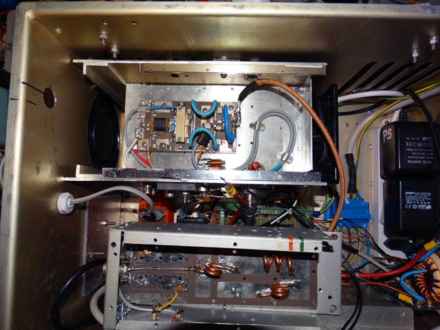
 For transmission i built, around a pallet with MRFE6VP1K25 and a D1-U-W2000 Murata Power Supply (50 V, 35 A), a remote controlled PA. Idd current, temperature of heat sink and that
near the Mosfet, direct RF Power, reflected RF as well as commands and alarms come to schack in analog way or as switched lines.
For transmission i built, around a pallet with MRFE6VP1K25 and a D1-U-W2000 Murata Power Supply (50 V, 35 A), a remote controlled PA. Idd current, temperature of heat sink and that
near the Mosfet, direct RF Power, reflected RF as well as commands and alarms come to schack in analog way or as switched lines.
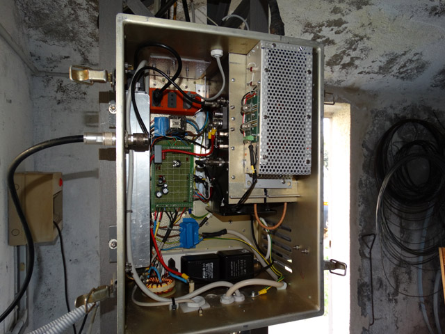
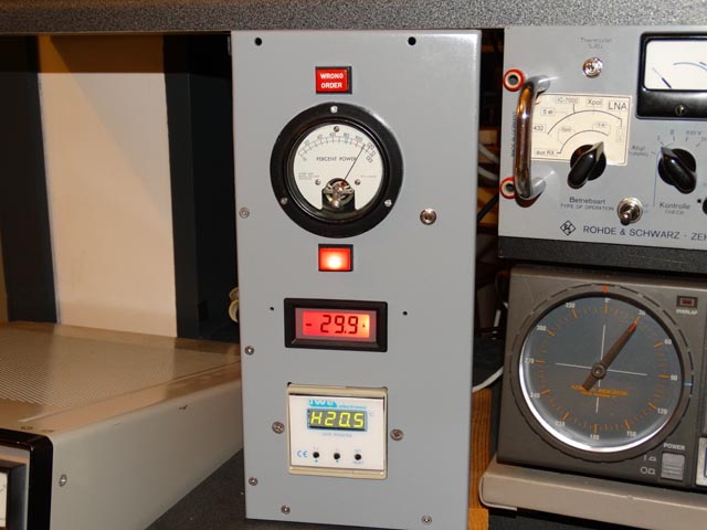
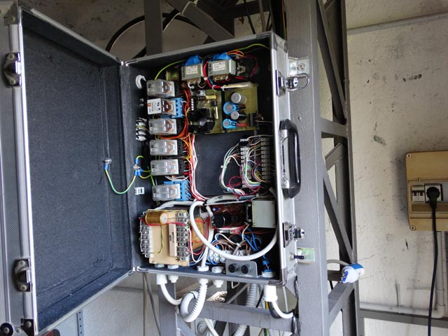 As accessories a command panel with sequencer, analog Azimuth Indicator (50 Hz Sincro) as well as AZ EL digital display is connected to a remote box with power supplies, relais for motors,
local command of the rotators and so on.....a lot of conductors, cables, connection boxes.....maybe too much, but i enjoy myself that way.
As accessories a command panel with sequencer, analog Azimuth Indicator (50 Hz Sincro) as well as AZ EL digital display is connected to a remote box with power supplies, relais for motors,
local command of the rotators and so on.....a lot of conductors, cables, connection boxes.....maybe too much, but i enjoy myself that way.
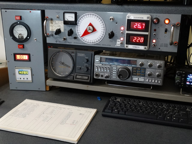 An old Yaesu FT-726 at the moment as exciter supported by an additional amplifier to reach the 4-5 Watts required by the PA after the long transmission line.
On PC i use presently MAP65 direct, with a second PC for WSJT if necessary.
An old Yaesu FT-726 at the moment as exciter supported by an additional amplifier to reach the 4-5 Watts required by the PA after the long transmission line.
On PC i use presently MAP65 direct, with a second PC for WSJT if necessary.
 That's all at the moment
73 de Mauro, IK6CAK
That's all at the moment
73 de Mauro, IK6CAK