By Claudio Pozzi, IK2PII - April 2004
The Siemens D2057 is a cheap and old selective
level meter, useful as test equipment but not as LF receiver.
I don't have the the manual or the schematics, but it's a very interesting test equipment for RF field measures, filters tuning and antenna return loss measurements. Also I don't have the W2057 level oscillator (but I have the user manual of this one, thanks to the Murphy law of course).
Inside the instrument, under a window cutted into one shield, there are two 2 mm diameter test points, red and black, where is present the buffered VFO signal. I discovered that this signal is 2.4 MHz higher than the received frequency, buffered but high impedance source. Red is signal, black is ground.
WARNING! the Siemens D2057 chassis ground is wired to positive supply voltage and there is no main AC power ground wired.
One hole was drilled into the front panel, one BNC connector was added
and the local oscillator signal, ranging between 2.4 to 4 MHz, was
driven outside the D2057 with a thin coax cable. It's now possible to
read the tuned frequency using a digital frequency meter.
And it's now time to build my tracking generator.
The kernel is the double balanced diode mixer
ANZAC MD108, but others DBM can replace this one. All the three ports
are connected to 4dB pads for resistive 50 ohms termination. The pads
can be changed a little for output level adjustment.
Q1 and Q3 are the VFO buffer amplifier, borrowed from M0BMU project,
with no voltage gain.
The IF 2 MHz low pass filter is composed by L1, L2, C13, C14 and
C15. The inductors L1 and L2 are 35 turns on Amidon T50-2 toroid cores.
Q4 and Q2 are the post mixer amplifier, also borrowed from M0BMU Bandpass Receiving Loop Antennas article. The gain is about 20 dB. (TNX Jim Moritz for yours projects).
U1 is the local oscillator. U1b oscillate at the IF selective level
meter frequency, it's not a very good local oscillator but performs
well in this project.
CV1 and C12 must be chosen for stable
oscillation, ready startup and correct frequency.
There is matter for
some improvements here. I think that a xtal at 4.8 MHz and a flip-flop
by two divider between U1c and U1d,e,f provide a better square wave to
the mixer. The oscillator also can be substituted with a transistor
Colpitts one.
U1d,e and f boost the square wave local oscillator up to more than +10 dBm (see "Experimental Methods in RF Design", ARRL 2003, page 4.16). The diode DBM mixers performs well with square wave local oscillator, no 2nd harmonic of L.O. was seen at the output of the mixer.
The IF port of the mixer is followed by the lowpass filter and by the post mixer amplifier. The output level is -10 dBu or 0 dBm about.
Measure the RF level at the RF port of the DBM, the level should be not more than -10 dBm, or 200 mV peak to peak.
To measure the LO oscillator level at the the LO port of the DBM it's better to disconnect the DBM from the 4 dB pad and solder a 50 ohm resistor between R23-R25 junction and ground. The square wave should be about 1 V peak to peak and can be adjusted changing the R22 resistor.
Connect the J2 output to the unbalanced input of the D2057 and tune CV1 for the maximum level. Verify that the level is constant between +- 1 dB from 5 kHz to 1600 kHz. It's now possible adjust the output level of the tracking generator, if you want, tuning the 4 dB pad at the IF port of the DBM mixer. The post mixer amplifier can be operated up to -10 dBu output level, i.e. about 0 dBm.
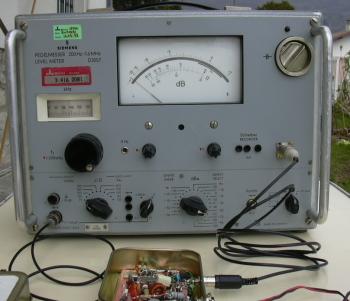
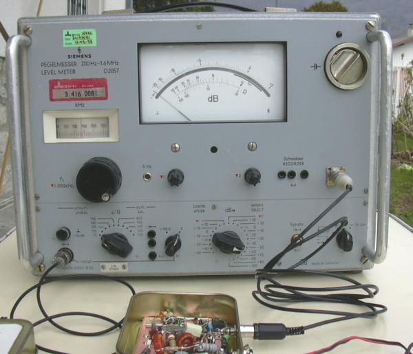 Siemens D2057 selective level meter with tracking generator |
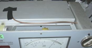 Siemens D2057 internal view of LO signal pick up |
 |
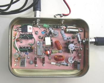 Tracking generator |
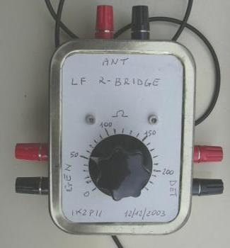 LF resistance bridge |