IK1HGE 432Mhz Quagi
Because of the several pictures, the complete download of this page might require some minutes. Be patient. You might want to read the text, in the meanwhile...
--------------------
I like electronics, telecommunications, photography, playing various instruments, programming... There are a couple of recent projects that I'd like to show to you. Let's begin with a 432 Mhz Quagi antenna.
I tried N6NB's
project but it didn't work well. Actually, there were some differences
from the original project: for the Driven Element and the reflector, I used
1.8mm solid copper wire (the one for coils or transformers) because, at least
in Italy, the old insulated #12 TW solid copper wire is too hard to be found.
Furthermore, the Directors diameter was 4mm instead of 3mm. Probably these
differences resulted in unacceptable Standing Wave Ratio, as you can see here below:
Fig. 1 Experimental SWR curve obtained with N6NB's design (materials as specified in the text above) Someone suggested me to optimize the antenna through NEC2, and... here you are the first results. This Quagi is optimized for 432.2Mhz operation,
however it works well in a quite wide range of frequency. All following data
are obtained through 4NEC2D v. 5.3.2 by Arie. The protype behaves better than I expected,
but it seems that the Driven Element requires a little adjustement due to
mounting approximations and to the coating of the copper wire. In my prototype,
the Driven Element required to be shortened of about 3mm. I suggest to: 1) Build the antenna by using
the design data here below 2) Run a SWR curve 3) Adjust the DE length. An estimation
of the new length is: DE(new) = DE(old) * fSWRmin/432.2 where fSWRmin
is the new frequency in MHz of minimum SWR. However the actual length depends
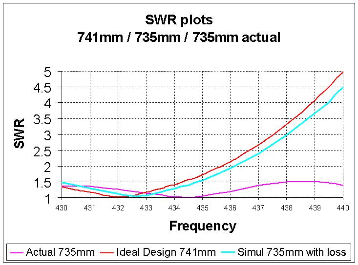
on your peculiar construction, thus take it easy and don't cut too much! I put some experimental
results and the pictures of the prototype at the bottom of this page. I only
regret that I did not record the SWR curves taken when the Driven Element was
741mm and 738mm long, however you can see that with 735mm the minimum SWR is
@ 434.5MHz. You can also see the comparison to a simulated antenna with 735mm
DE which includes loss due to non-ideal material. 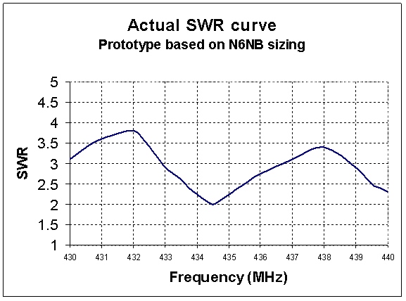
Have fun!
| Parameter | Value | Unit (Conditions) |
| Frequency |
432.2
|
MHz |
| Forward Gain |
13.77
|
dBi |
| SWR |
1:1.03
|
(432.2 MHz) |
| SWR (min) |
1.01
|
(432 MHz) |
| Bandwidth |
430-434
|
MHz (SWR<1.4:1) |
| Take off angle |
1.8
|
Degrees above good ground (Height about 8 wavelengths) |
Table 1 Antenna performance (MOM simulation)
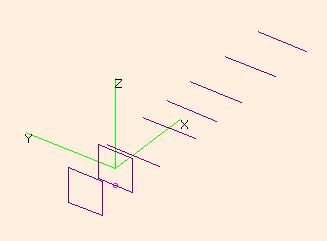
Fig. 2 Structure of the quagi antenna
| Quads copper wire diameter | 0.0018 | Directors aluminum rods diameter | 0.004 | Boom (wood) 1.50 |
| Element | Length | Position | Spacing | |
| RE | 0.76215 | -0.22904 | DE-RE | 0.22904 |
| DE | 0.7413 | 0 | DE-DE | 0 |
| D1 | 0.29365 |
0.13093 | DE-D1 | 0.13093 |
| D2 | 0.29213 |
0.40783 | D1-D2 | 0.2769 |
| D3 | 0.28042 |
0.57751 | D2-D3 | 0.16968 |
| D4 | 0.28618 |
0.7632 | D3-D4 | 0.18569 |
| D5 | 0.28384 | 1.0228 | D4-D5 | 0.2596 |
| D6 | 0.27414 | 1.2687 | D5-D6 | 0.2459 |
Table 2 Design information (meters)
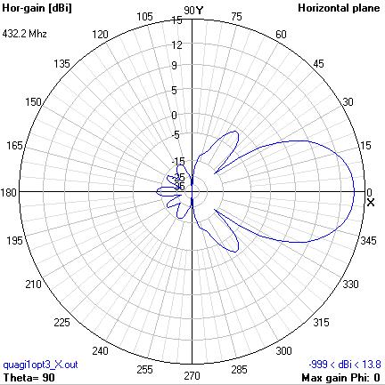
Fig. 3 Vertical (Elevation) pattern in free space
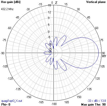
Fig. 4 Horizontal pattern in free space
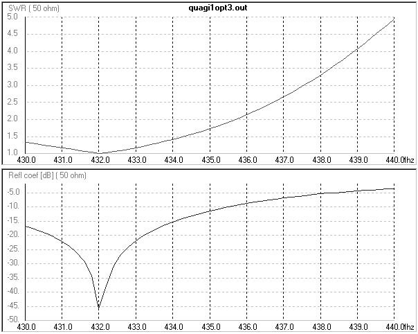
Fig. 5 SWR and reflection coefficient charts
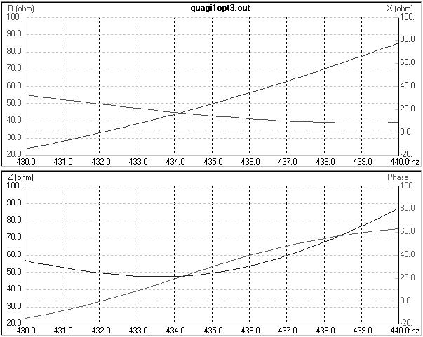
Fig. 6 Impedance charts: Resistance,Reactance (top) and Impedance,Phase (bottom)
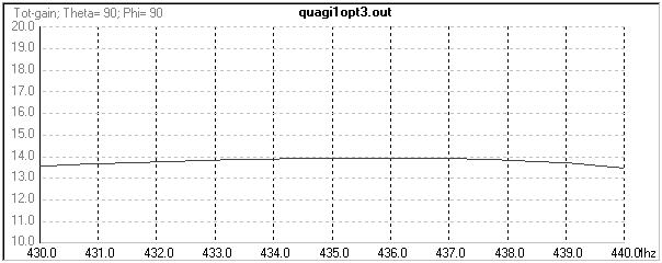
Fig. 7 Total Gain vs. Frequency
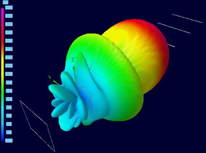
Fig. 8 IK1HGE 432MHz 8el Quagi - 3D horizontal gain plot
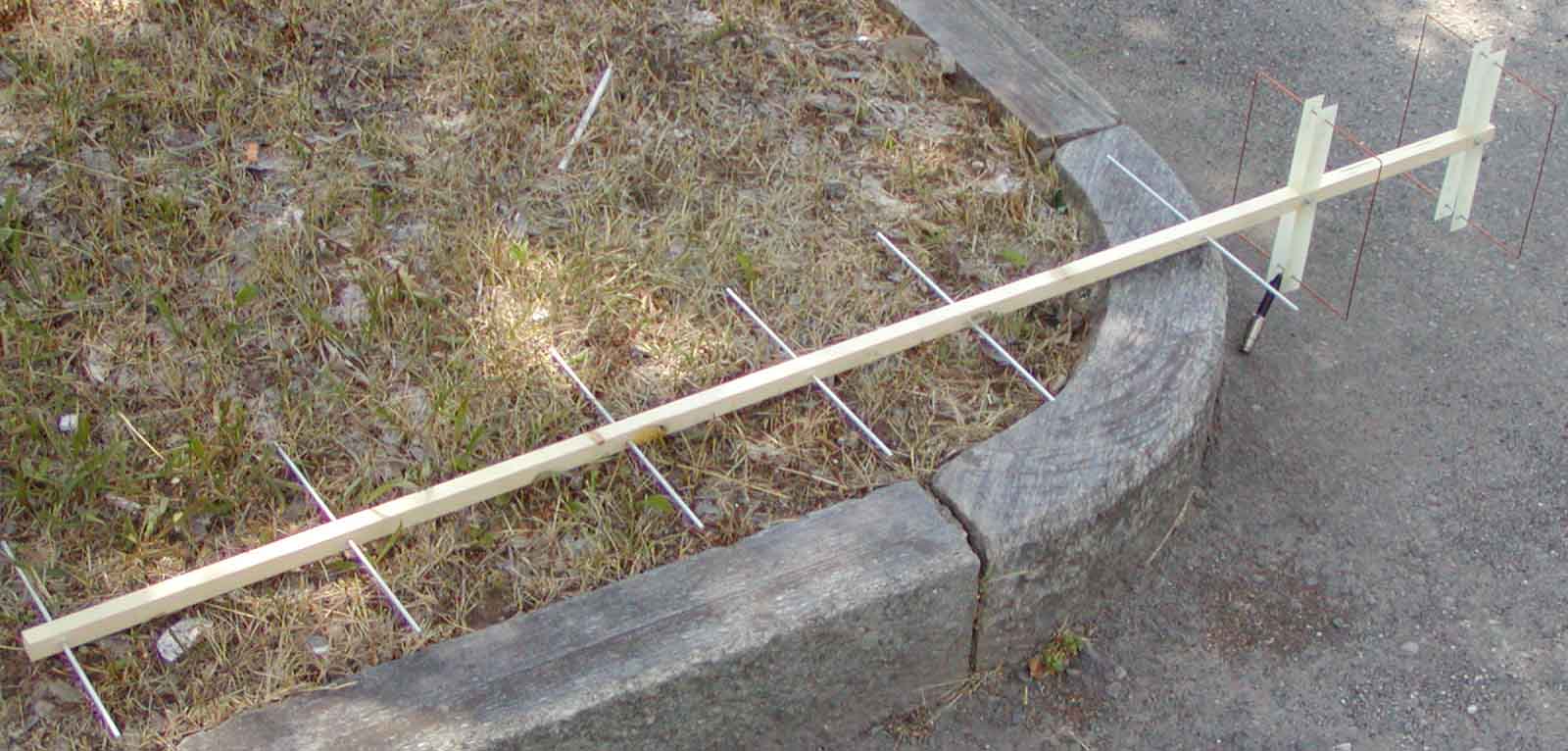
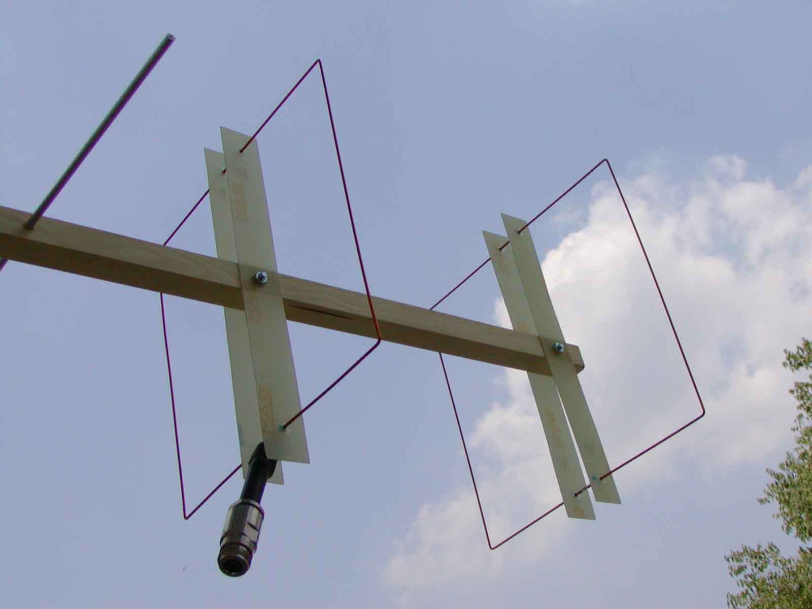
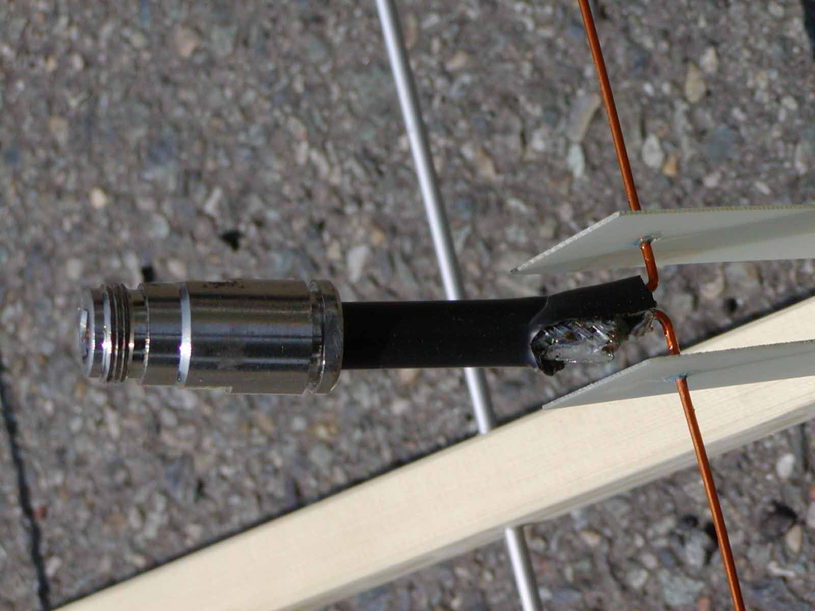
The construction details are described in N6NB's article, in the ARRL Antenna Handbook and in many places on the net. Just search for "Quagi".
Here below, find some suggestions and some pictures of my prototype.