RF 1
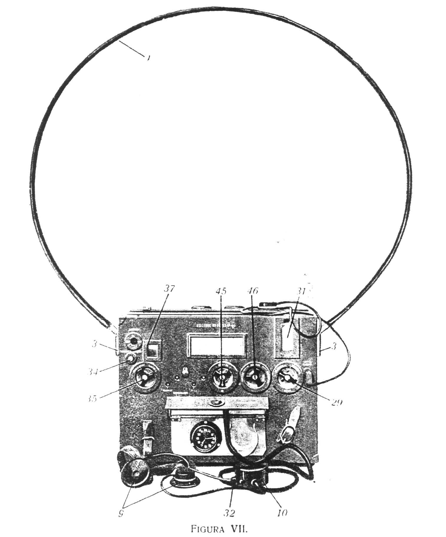
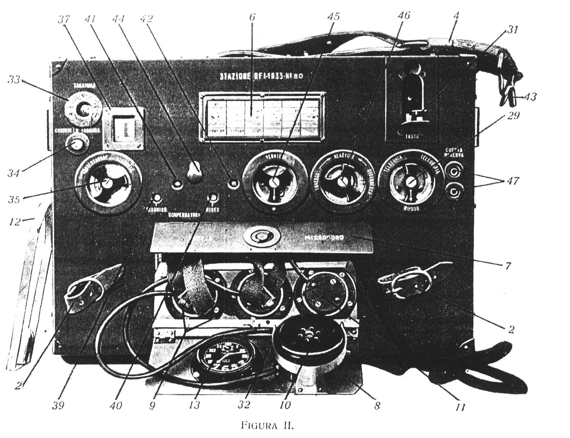
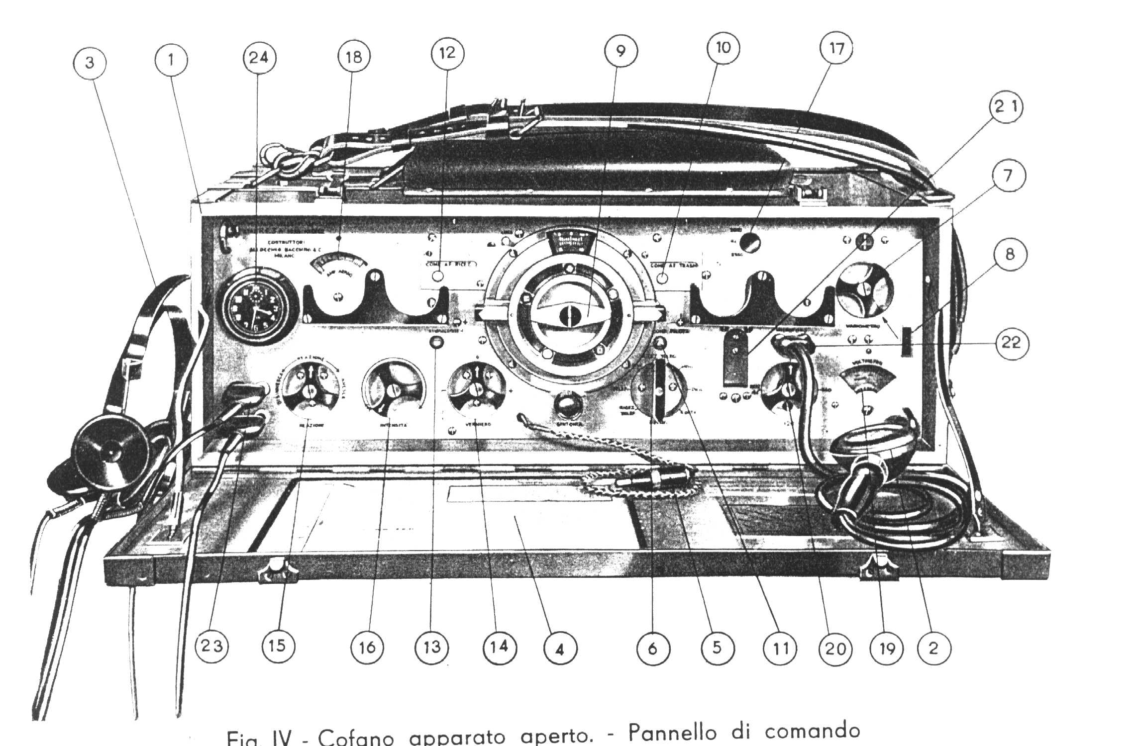
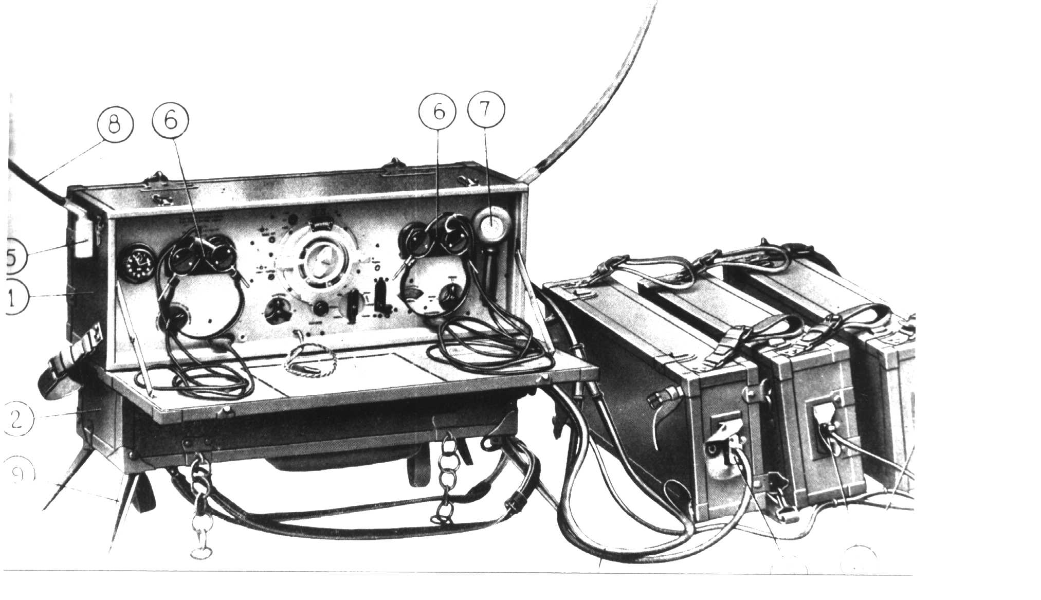
Radio station. Manpack. Low power ground station for infantry communications inside the small units in the range of 3-10 Km. It has been the standard italian manpack. Built in many versions and from several manufacturers.Year : 1935
Frequency Range : 2,500 - 2,770 kHz
Facilities : CW and RT
Receiver Circuit (Valves) : RF amplifier (RSAF), Detector (RRAF) + 2 AF (RRBF)
Transmitter (Valves): MO (TR1-2), Mod. (RRBF)
RF Output : 0.8 W
Aerial : Loop
Power supply : Multivoltages dry batterie.
Models:
Mod.33 Manufacturer OMT
Mod.36 Manufacturer CGE - Clock on the right of the front panel. It has a lamp antenna tuning indicator. Improvement on AF stage.
Mod.33 1940 serie. Manufacturer IRRADIO. Same as Mod.36
Mod.36 1940 serie. Manufacturer CGE. Same as Mod.36 with small circuit improvements.
RF 1CA
Radio station. Transceiver. Designed for tank purpose and working on the same range of frequency of German tank. Intensively utilized in N.Afrika. It was also a version for ground use called "RF 1CA in cofani" where the complete unit were in 3 chests including accessories and antenna. Range 3-12 Km.Year : 1940
Frequency Range : 27.2 - 33.4 MHz
Presettable frequencies. 4 channels.
Facilities : MCW, RT (AM), Interphone.
Receiver : Superheterodyne. 8 tubes (seven 6RV plus one 6TP)
Transmitter : MO (6TP), PA (6TP). Modulator/Interphone used same AF amplifier of the receiver section (6RV micro ampl.+6TP power amplif.)
RF Output : 8 W
Aerial : Rods (4 elements) for ground and whip for tank.
Combination:
Transceiver TR7, PSU type AL-1, Antenna tuner, RF Oscillator/calibrator, Accessories and antenna system.
Power supply : AL-1 - Dynamotor driven by 12 V storage batteries.

RF 1P
Radio station. Manpack. Set specially designed for Para troups. Very modern set using special Philips valves and numeric frequency readout. Manufacturer Allocchio Bacchini. Contained in two metal Boxes (Radio set, Battery compartment) and one bag (Antenna parts)Year : 1942
Frequency Range : 4,280 - 5,250 kHz.
Facilities : CW and RT
Receiver Circuit (Valves) : Superheterodyne using 5 valves D11F or D1F plus one D12f like AF amplifier that works also like modulator for TX section.
Transmitter (Valves): MO (D12F or D2F), PA (2x D12F or D2F), Mod. (AF section Receiver)
RF Output : 1 W
Aerial : Vertical. Short antenna 1.3 m for range 10-15 Km, Long antenna 5,6 m for range 20-40 Km Both have a capacitive hat.
Power supply : Multivoltages dry batteries contained in a suitable box.

RF 2
Radio station. Ground low power. Contained in two chestes: 1)Radio set 2)Batteries. In charge to Artillery groups for internal communications. Range 8-20 KmYear : 1935
Frequency Range : 2,778 - 4,285 kHz
Facilities : CW and RT
Receiver Circuit (Valves) : Superheterodyne RF ampl. (RSAF), Osc./Mixer (RRCF), 2xIF (RSAF), AF ampl.(RRBF)
Transmitter Circuit (Valves): MO (TR2), Mod. (RRBF)
RF Output : 4 W
Aerial : Loop
Power supply : Dry batteries contained in a separate chest.

RF 2CA
Radio station. Ground or tank installation. Used for communications among tanks squadron commanders. Usually mounted on "Carri comando (Command tank)" in parallel with the RF 1CA.Year : 1940
Frequency Range : 3.750 - 5.300 MHz
Presettable frequencies. 4 channels.
Facilities : MCW, RT (AM), Interphone.
Receiver Circuit : Superheterodyne. 7 tubes
Transmitter : MO PA. Modulator/Interphone AF stage receiver section
RF Output : 8 W
Aerial : Rods 2.7 m high.
Ground type Composition:
Transceiver TR4, PSU AL1, Antenna, Accessories bag, Cables and storage batteries.
Tank type composition:
Transceiver TR4, PSU AL1, Control box, Antenna, Antenna tuner, Cables, Accessories.
Power supply : AL1.

RF 3A
Radio station. Portable. In charge to mountain troups. Range 60-100 kmYear : 1936
Frequency Range : 1,840 - 2,515 kHz
Facilities : CW and RT
Receiver Circuit (Valves) : Superhet. IF = 333 kHz. RF ampl. (RSAF), Osc./Mixer (RRCF), 2xIF (RSAF), BFO (RRAF), AF ampl.(TR2)
Transmitter Circuit (Valves): MO (RRBF), PA (2x TP425), Mod. (RRBF+TR3)
RF Output : 7 W
Aerial : Inverted L, 40 m Dipole or vertical.
Power supply : Dry batteries contained into separate chests.
RF 3C
Radio station. Portable. Used from Armoured and Motorized units like fixed or semifixed station for inter units communications in the range of 20-50 km. Usually carried by a motocycle with a sidecar.Year : 1936
Frequency Range : 1,875 - 2,500 kHz
Facilities : CW and RT
Receiver Circuit (Valves) : Superhet. IF = 333 kHz. RF ampl. (RSAF), Osc./Mixer (RRCF), 2xIF (RSAF), AF ampl.(TR2)
Transmitter Circuit (Valves): MO (2x TR3), Mod. (RRBF+TR3)
RF Output : 5 W
Aerial : Loop
Power supply : Dry batteries contained in separate chests or pedal generator.
RF 3M
Radio station. Separate transmitter-Receiver. Vehicular installation usually on AFV. Range covered 40-70 KmYear : 1940
Frequency Range : 1.690 - 2.790 MHz
Presettable frequencies : 4 channels.
Facilities : CW, RT (AM).
Composition :
Receiver : RR 6
Transmitter: TS 2
Double PSU, Control box, ATU, Accessories, Antenna parts
RF Output : 35 W
Aerial : On move = 3.75 vertical with radial hats. Fix = 7 m vertical
Power supply : By dynamotors driven by 12 V storage batteriesof the vehicle.
On 1942 come out an updated model branded RF 3M2 Mod.42 with some internal improvement and different front panel.

RF 4
Radio station. Portable. Called also "Unificata" because it can replace the R4 and R4A. Used for communications among large units commands, and for aerocooperation. The station is divided in 2 chests: 1) Receiver, Transmitter, Controll panel; 2) PSU, Battery charger, accessories.Year : 1939
TX Frequency Range : 214 - 1,580 kHz
RX Frequency range : 220 - 4,400 kHz in 5 bands
Facilities : CW and RT
Receiver Circuit (Valves) : Superhet. 7 tubes type 6RV
Transmitter Circuit (Valves): MO(P C05), PA (2x P CO5) Mod.(3x 6RV)
RF Output : 25 W
Aerial : 20 m inverted L
Power supply : 12 V storage batteries. Mains for battery charger

RF 4D
Radio station. Portable. Similar to RF 4. Replacement for R4D but also for R4A.The station is divided in 2 chests: 1) Receiver, Transmitter, Controll panel; 2) Dynamotor PSU, Battery charger, accessories.Year : 1940
TX Frequency Range : 1,270 - 4,300 kHz in 3 bands
RX Frequency range : 220 - 4,400 kHz in 5 bands
Facilities : CW and RT
Receiver Circuit (Valves) : Superhet. 7 tubes type 6RV (same as RF 4)
Transmitter Circuit (Valves): MO(P C05), PA (2x P CO5) Mod.(3x 6RV)
RF Output : 25 W
Aerial : Dipole
Power supply : 12 V storage batteries. Mains for battery charger.
RFC 15GM
Radio station. Built for field operation in tropical environment.Year : 1940
Frequency Range : 2.5 - 10 MHz in 2 bands
Facilities : CW and RT
Receiver Circuit (Valves) : Superhet. 6 tubes type KF4
Transmitter Circuit (Valves): MO(5C15), PA (5C15), Mod.(5C15), Vox (KF4)
RF Output : 15 W
Aerial : Dipole
Pedal generator or engine driven rotary generator.

RF OC
Radio station. Separate receiver and transmitter. Portable. Tropicalized. Studied to be camel carried. Range 200-400 Km.Year : 1932
Frequency Range : 3.571 - 8.333 MHz.
TX crystal controlled.
Facilities : CW and RT
Receiver Circuit (Valves) : RF Ampl. (RSAF), Detec. (RSAF), AF Preamp. (RRBF), AF Ampl. (2x RT2)
Transmitter Circuit (Valves): MO(TU430), PA (RTS4), Mod.(RRBF).
RF Output : 10 W
Aerial : Slope
Pedal generator or dry batteries.