PARASET PROJECT
by IK0MOZ
Starting date Nov. 04 2001
Updated on : Nov 20 2001 : Added photos and drawings
Updated on Dec. 5 2001 : Added drawings and photos
Added second page on Feb.25 2002
Warning : Due to large quantity of photos and drawings the speed
of the page is quite low.
I beg your pardon, but to keep an acceptable images quality no other
possibility.
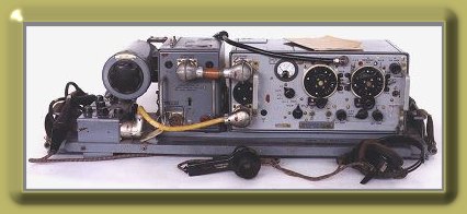
What is the PARASET ?
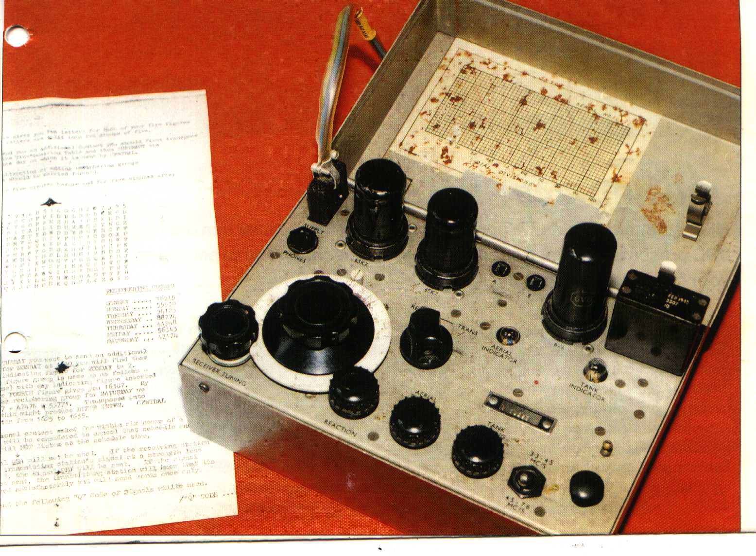
The PARASET is a small British "Spy set" transceiver
supplied during the WW2 to the Resistence forces mainly in France, Belgium
and Netherland.
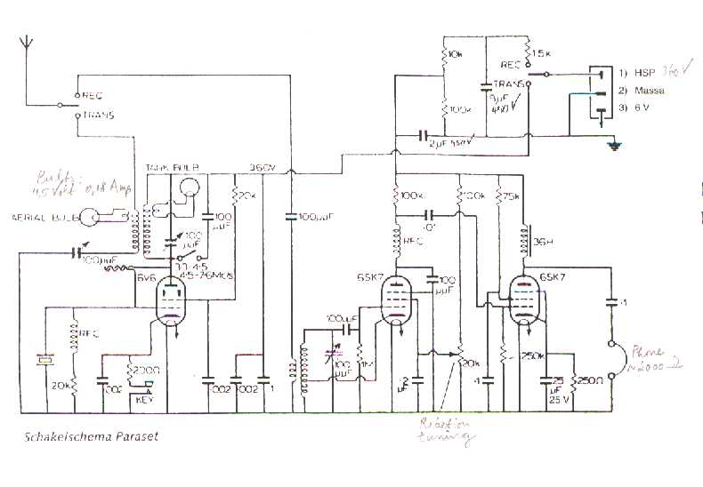
It uses 3 metal tubes :
1) 6SK7 - Detector
2) 6SK7 - AF Amplifier
3) 6V6 - Cristall Oscillator/P.Amplifier
The range covered from the receiver is 3.2 - 8 MHz
on AM and CW modes.
The transmitter is cristall controlled and works on the
same receiver range.
The power output is around 5-7 W on CW mode only.
The set were supplied by a 6 Vdc vibrator type PSU.
For Its semplicity the set can be easily " replicated"
and many replica are already in use.
Usually this kind of work starts using the ON5LJ series
of drawings, in progress some differences are due to different availability
of the necessary parts.
We will do the same, and will follow step by step the
construction of 3 sets. In these steps will be possible find some suggestion
like to solve possible problems.
I hope that this idea will be of interest and if you decide
to start with this adventure let us know, your experiences will be added
to these pages.
We are thinking also to open a PARASET FAQ section
and mainly to activate a frequency entirely devoted to PARASET
and Paraset replica tests.
To end we have to thank Jo Scholtes - ON9CFJ
that supplied to us a lot of documentations, photos and details of
his original Paraset.
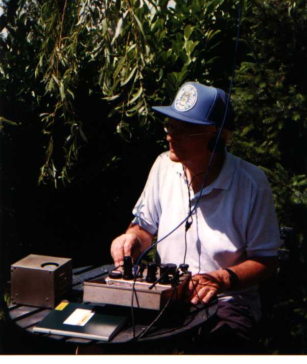
Jo - ON9CFJ in full action
June 2001
The story starts during the ADMM when in a QSO Jo
(ON9CFJ) asked to me if for the competition were valid also a "Replica"
set assembled with surplus parts.
After my negative answer being the argument exciting I asked
for details because I were personally interested.
Jo clarified to me that the replica were a Paraset
and by return he will send to me some drawings showing all details for the
set construction.
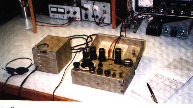
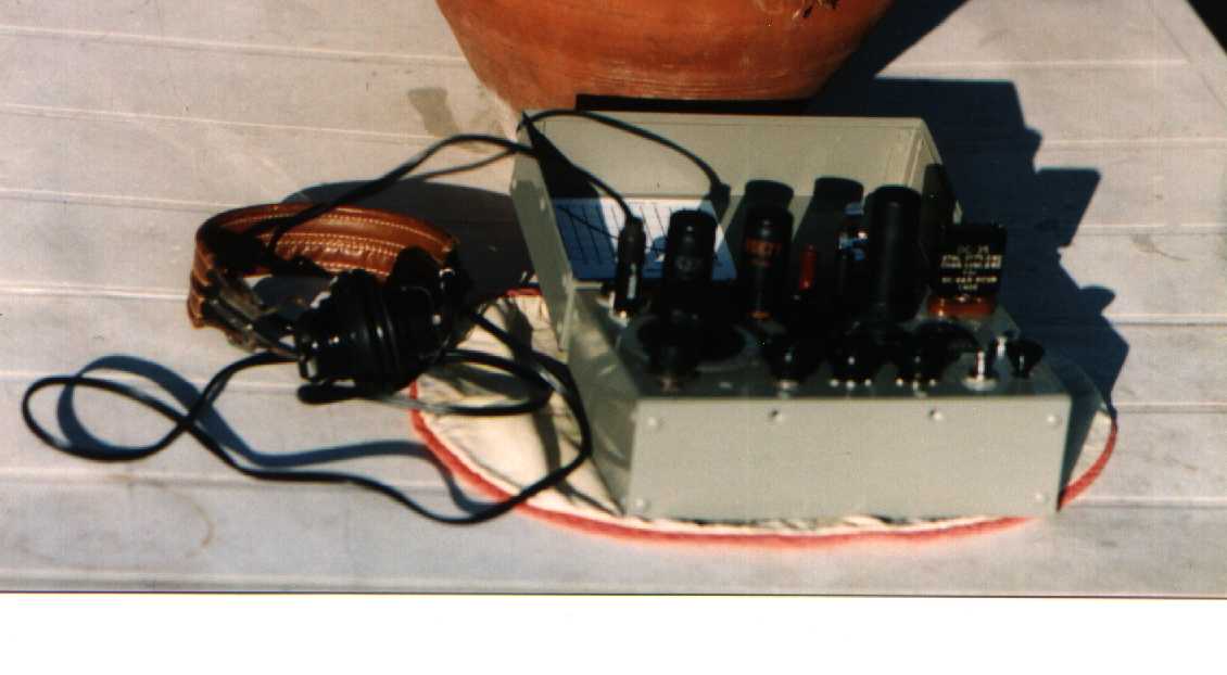
The ON9CFJ complete original Paraset, on the left the Vibrator
PSU
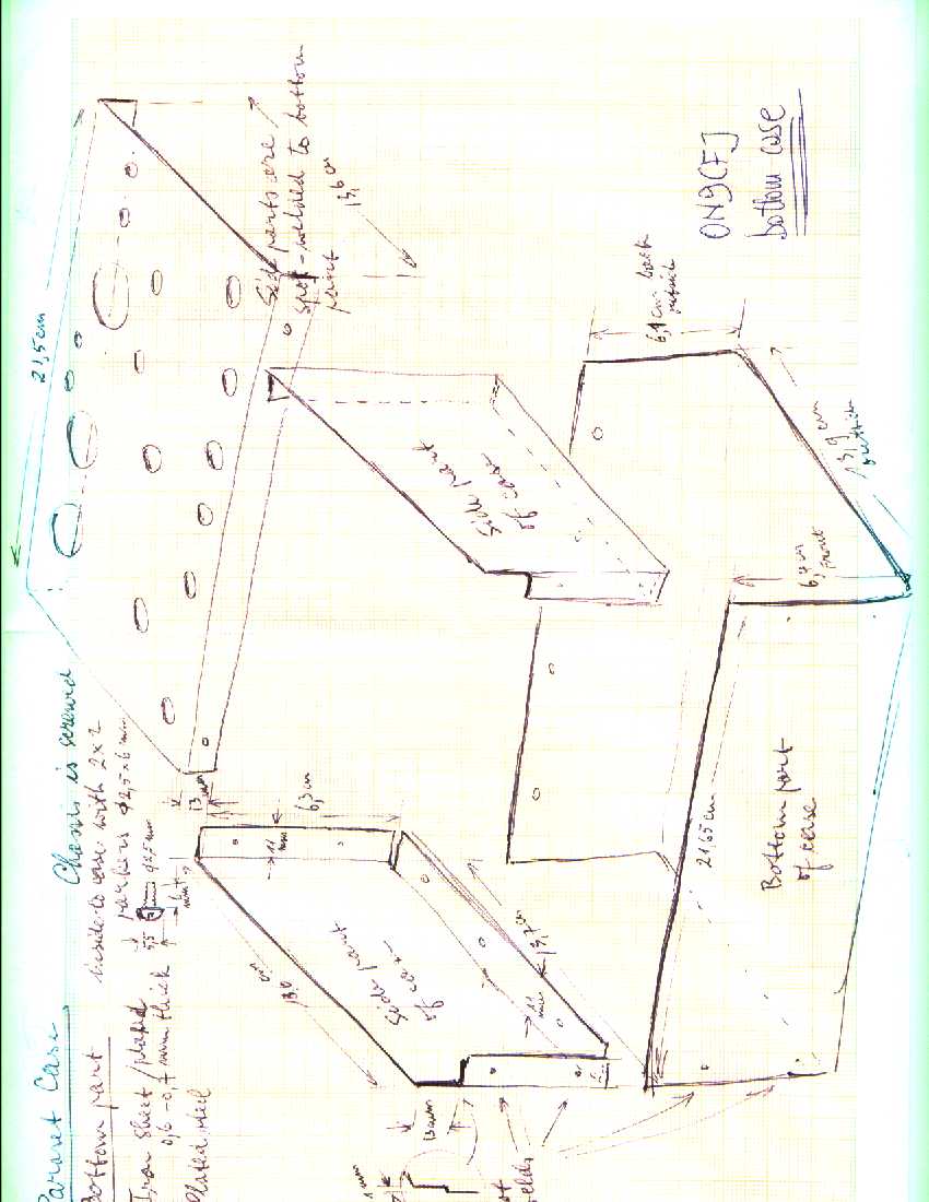
After some days arrives by mail an ON9CFJ envelop containing
1) Series of Paraset drawings (originator ON5LJ) :
JULY 2001
Around the end of July I made a check about the project
status :
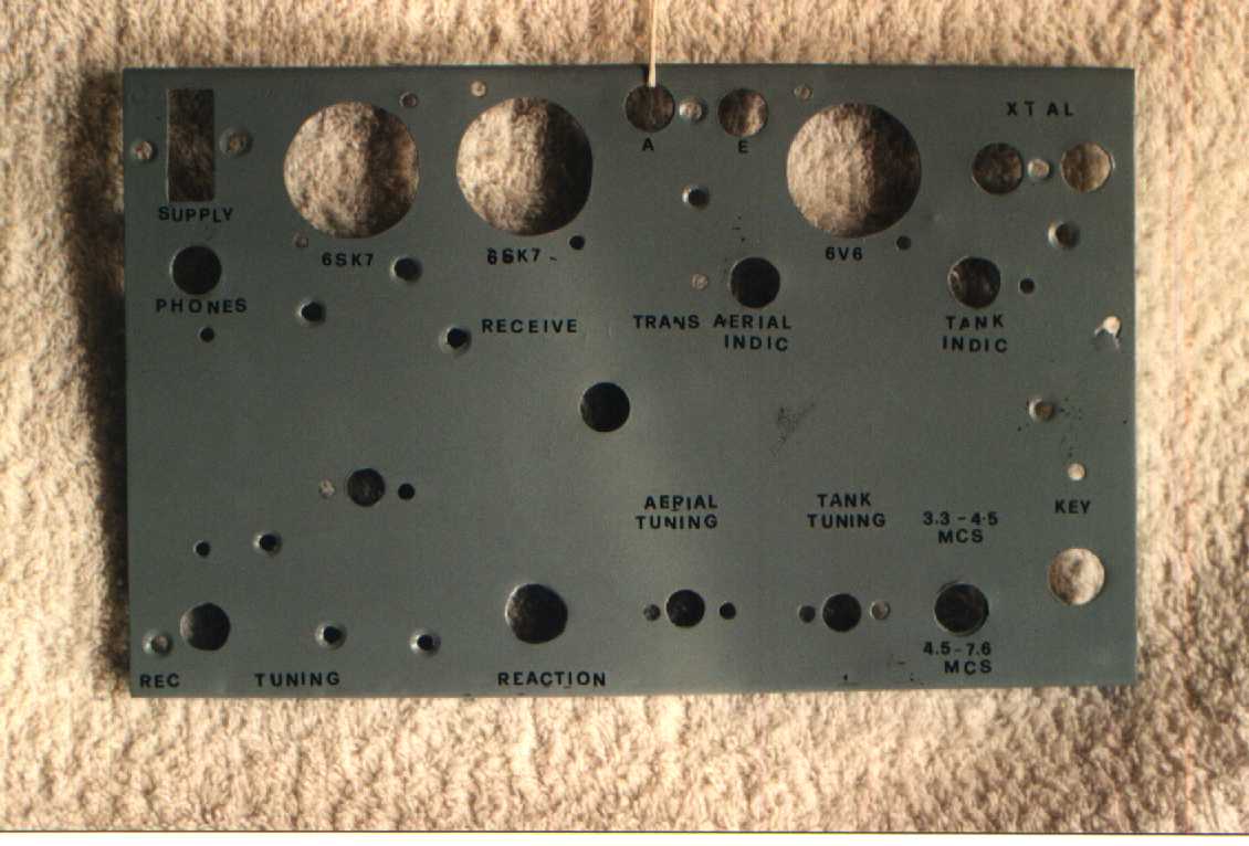
IK0MOZ : Panel made in 0.7 mm zinc plated iron sheet.
The holes on this panel are more then I see on the drawing. The 0.7
thikness of the panel is too low it is better choose 1 mm. I start to collect
the parts, this is the situation : Variable capacitors, crystal holder,
antenna/ground connector, RX coil and knobs recovery from a BC610 Tuning
Unit. Terminals board and lamp holders from RS catalog (433-755) and
( ). Problems RF and AF Impedance, problem also on
tuning indicator and slow motion system.
I0BR : Panel made in 1.5 mm aluminium. Variable capacitors,
crystal and antenna connectors from the BC610 TU. Knobs from BC312.
Key completed (very fine). 36 H impedance done using a AF output transformer
adding 0.1 mm wire to maximum possible. HF choke he will use 2 Geloso
parts. Components : many of surplus origin and other using modern
components but put into surplus case. Tuning disk original, slow motion done
using a potentiometer spindle.
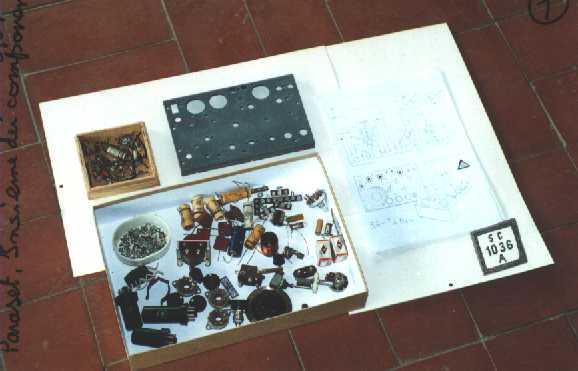
Panel and collected parts from I0BR
IK5FUZ : Case completed including hinge and spring tube
holders. He is going to start with the front panel (Aluminium). Tuning disk
and slow motion original. He is collecting the electrical components.
Some questions:
1) Tubes socket type ?
2) Panel and case color ?
3) Case has some handle ?
4) Some inside photo
5) Key drawing not clear
I7KVG : No info
Before summer vacatios I sent to Jo - ON9CFJ the FUZ and
other questions
SEPTEMBER 2001
e-mail from ON9CFJ :
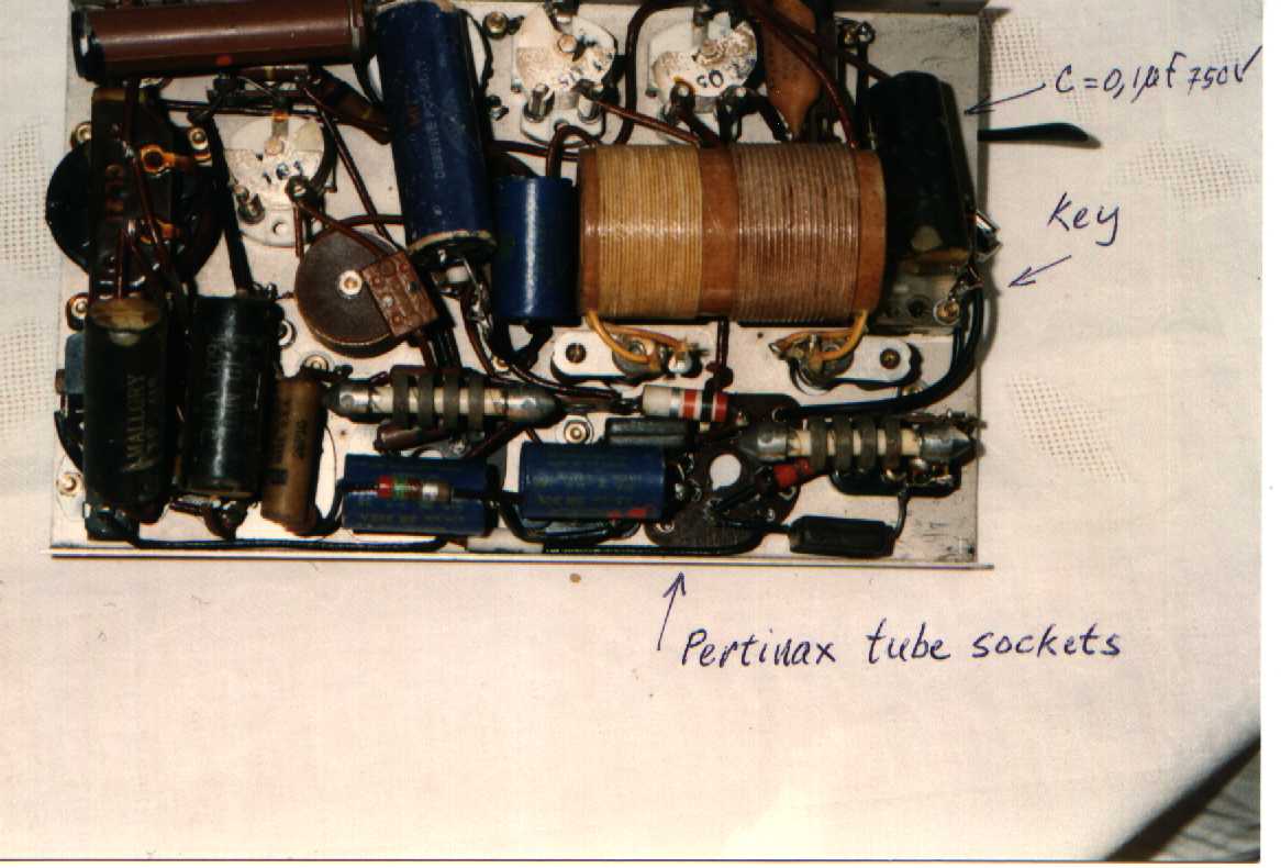
1) Tube sockets are in 1 mm Pertinax
2) Panel and case color is silver-grey
3) No handle
4) Will follow by mail new inside photos.
I0BR : Noted some errors on RX section layout.
The power for 1.5 k and 10 k resistors on supply line are
not correct.
Home made the coil support for TX gluing several carton
sheets on a 35 mm core. After the tube has been fixed and hardned with transformer
compound. Final result very similar to the original.
He started with electrical assembling. Wires cotton covered.
Noted small space available.
IK5FUZ : Panel completed. He is proceding with the electrical
assembling. Tube sockets used in pertinax. TX coil different diameter
but with the same inductance then original. Lamps used 3.5 V 200 mA because
the original are not available Problem on the key and asks for a better
drawing and if the case have some lock system
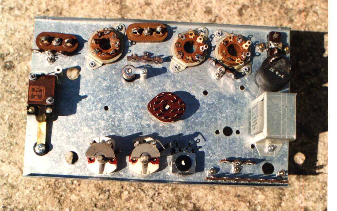
IK0MOZ : Front panel paintend and silkscreened. The lettering
has been made using 3.7 mm Letraset
Mechanical assembling done. Found all parts (Modern and
Surplus) less the RF chokes and tubes. The AF impedance made using a
3.5 VA 220/6 Vca transformer. The inductance is 18 H instead the 36 H required.
I find also an old TV audio output transformer with 33 H inductance and
R 900 Ohm, but being the fixing holes in different position, I will start
with the first solution. if necessary I will change the item in a second
step.
On middle of september arrives a new envelope from
ON9CFJ including :
1) A detailed drawing of the key (Originator ON9CFJ)
2) Additional photos of his Paraset .
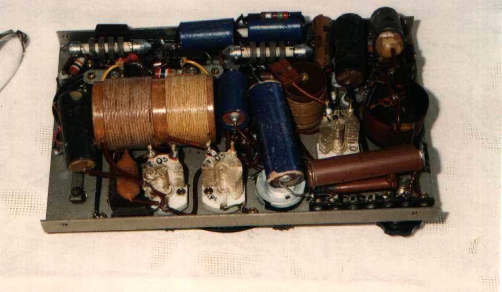
IK0MOZ : Completely assembled the TX section. Found
new error on the TX layout (on the supply line). HF chokes problem
momentary solved using RS coils cat. N° .........
Found tubes from surplus dealer ESCO - 6V6
is glass type.
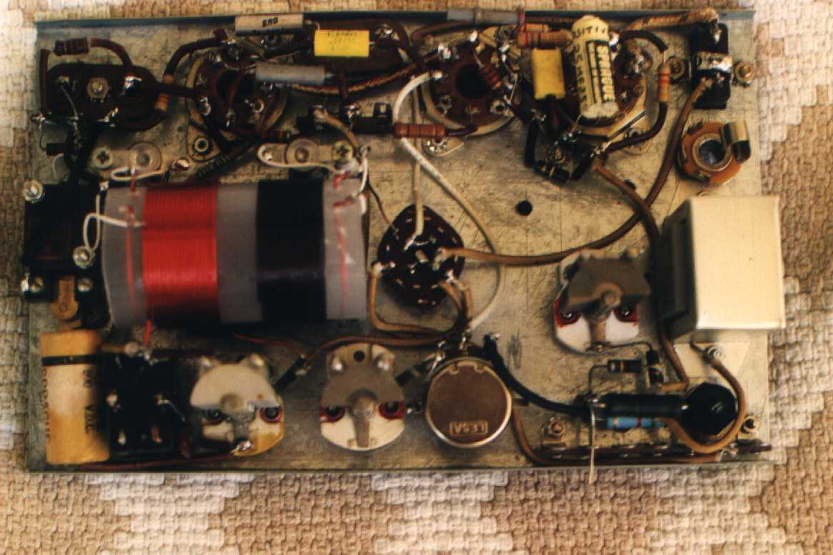
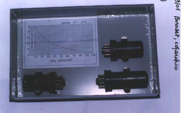
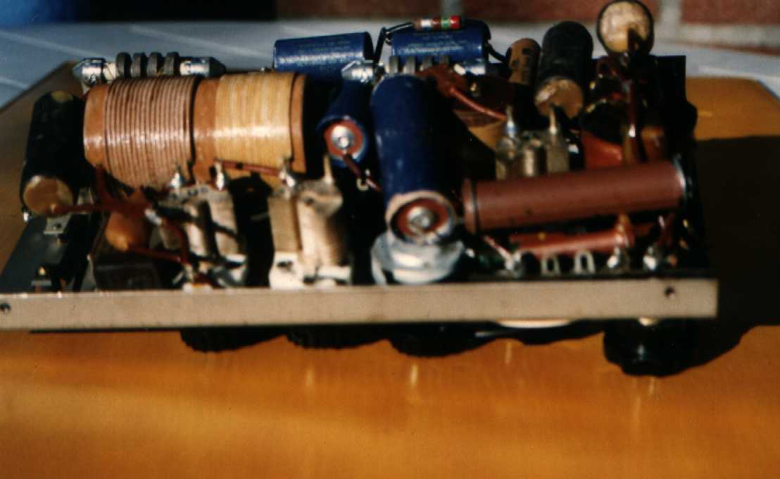
TX section completed.. In the center the RX coil
is missing.

TX section different view. Is possible see the
"Made I0BR" key, and the 0.1 MF 750 V Sprague capacitor.
OCTOBER 2001
ON9CFJ via E-mail confirms the errors in the schematics
and confirm that in the case there are not locking system.
I0BR set completed less case. Fixed a sked for on air
tests
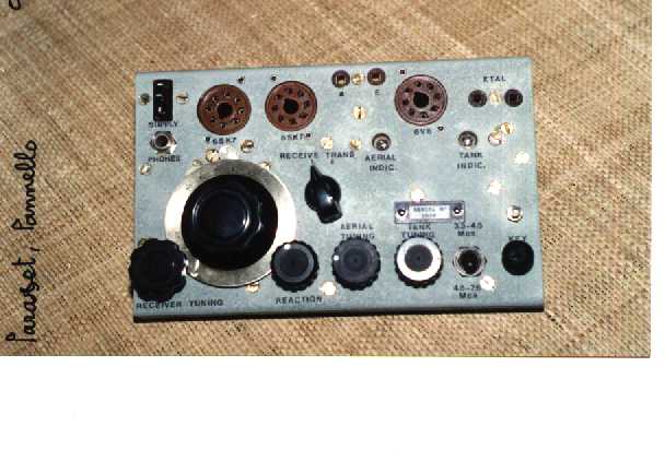
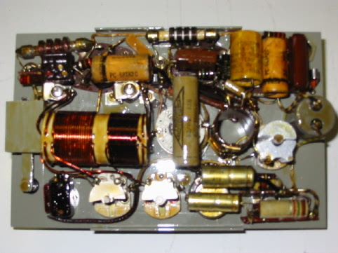
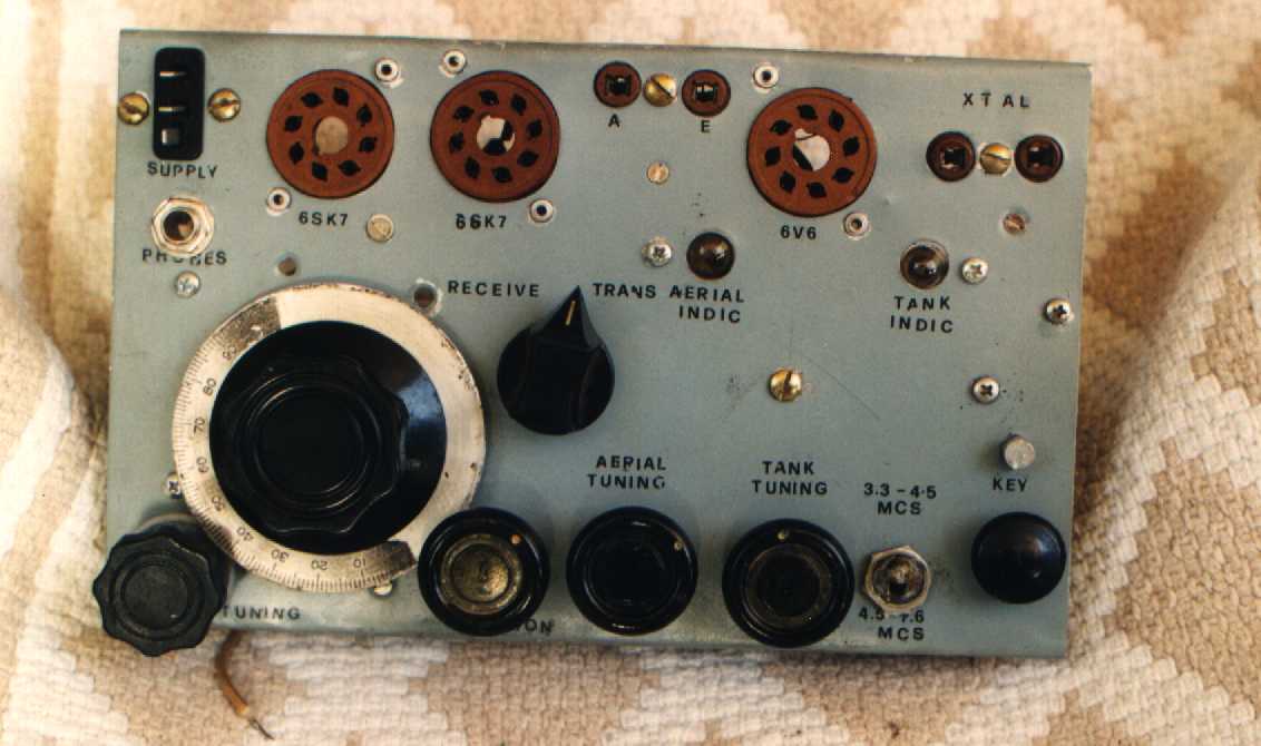
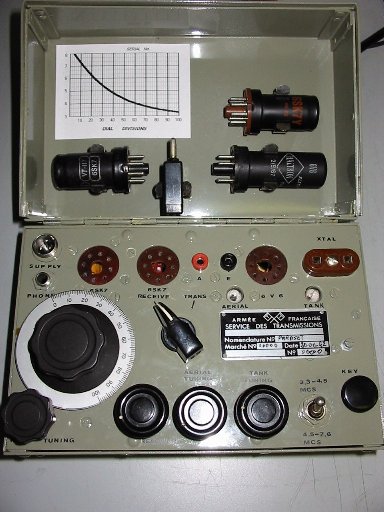
Front panel of the I0BR set
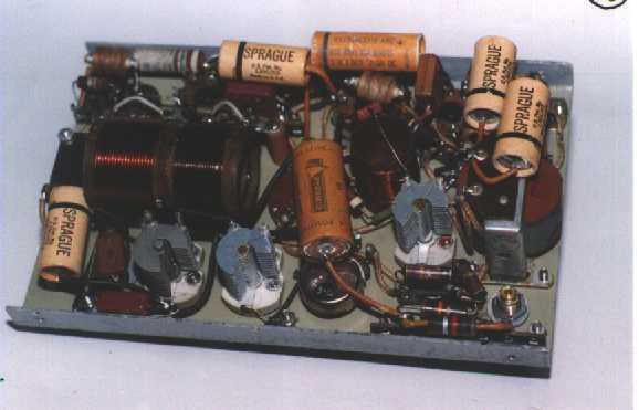
the same from the inside
The Paraset has been built using all surplus parts. The
final result is very good.
Pout on 80 m. around 7 W, POut on 40 m around 5 W.
TX tuning very easy. Receiver quite broad reaction control very critical.
Roberto shortened the variable capacitors because the max capacity were around
120 pF instead of the required 100 pF. The adjustments has been easily done
taking away the last 4 blades of the capacitors.
For the tests has been used some FT243 series crystals.
It has been also tested some modern TV crystals with the max Power of
1 W. The possibility to use this kind of very cheap and common crystals
has been rejected.
On late afternoon we make the on air test. Distance betwen
our QTH around 60 Km.
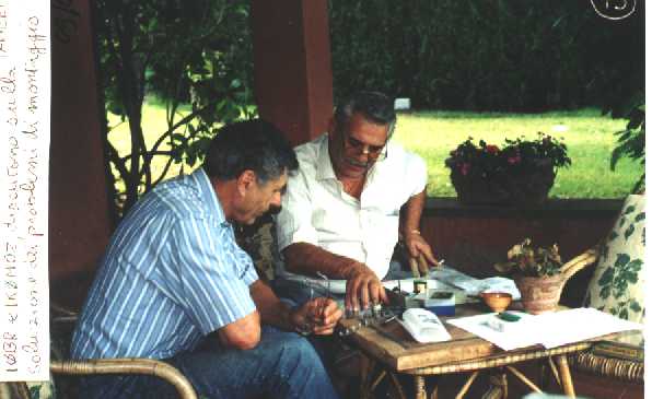
I0BR/Roberto (on the left) and IK0MOZ/Mario. Subject : Paraset to do
list
I use my SEG100 and send a long serie of V to allow
the receiver tuning. When I pass on receive mode I can ear very clearly
the I0BR sigs. RST around 579 absolutely no chirp. We made a short QSO without
problem.
IK5FUZ : Also Alberto finished the set it is missing
only the lettering on the panel. He made al the test and noted the same
Roberto results. Confirm the criticity of the receiving section, but he found
very stable. He send to me the first photosask to me .
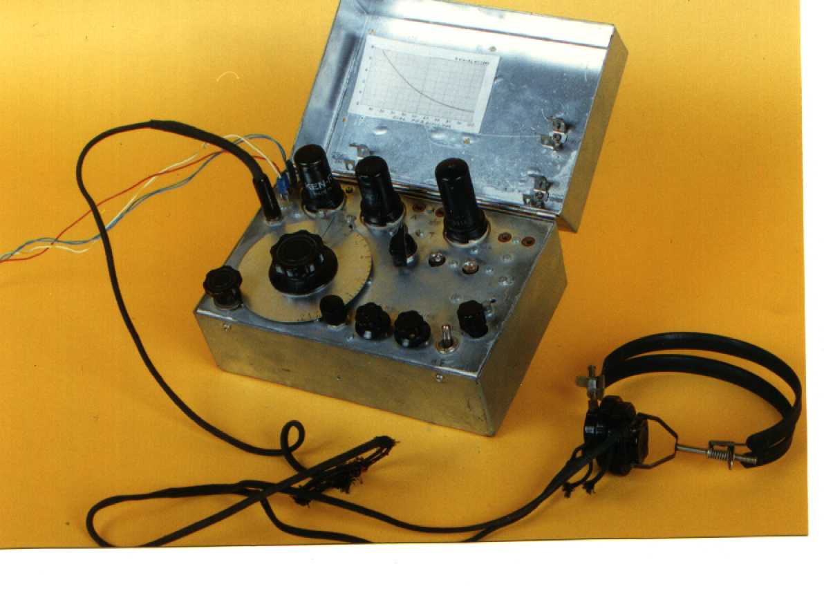
IK5FUZ / Alberto complete set
and seen from the inside
IK0QDQ/Edoardo ask to me all the Paraset documentation,
after analisys he will decide if start with the project.
IK0MOZ : Set completed. Still problem on slow motion drive.
Built a PSU using 2 tranformers : 1) 220/6 Vca for filaments. 2) 220/220
Vca for HT. Rectifing (4x1N4007) and filtering (130 MF 450 V) the secondary
220 V the DC is around 300 V. In this condition the TX Pout is
around 4 W. Also the receiver is OK and noted the same tuning difficulty
already mentioned from I0BR and IK5FUZ. The reaction controll is quite
difficult and need practice.
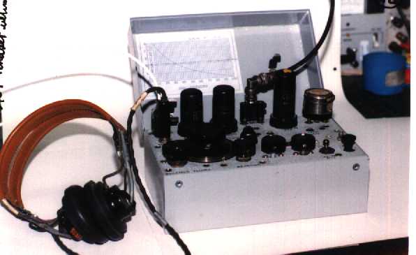
IK0MOZ complete Paraset , but not yet case
Built the case using aluminium. Sides fixed with screws.
Missing the lid
I0BR : Buil the case including tube holders and tuning
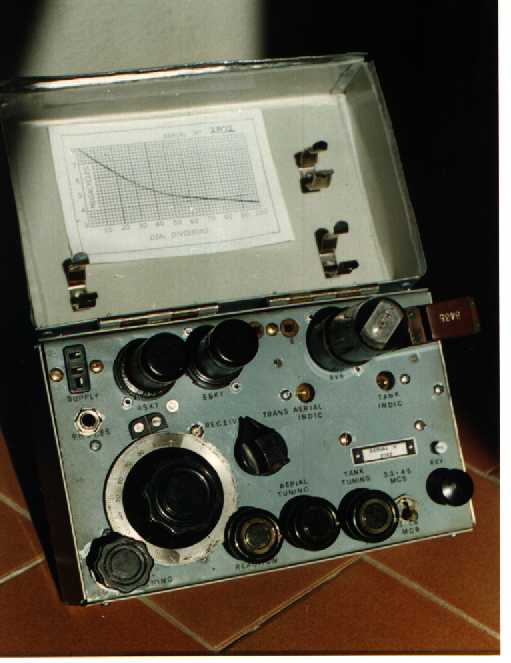
table. First PARASET Replica made in Italy.
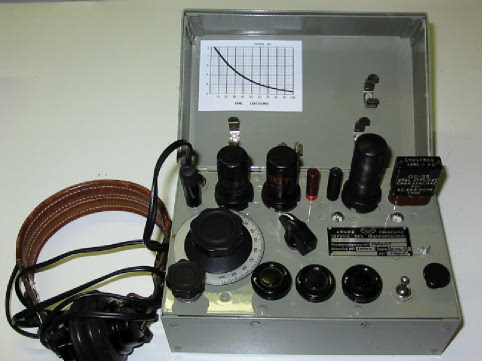
I0BR set - The cover with tubes and tuning table
I0BR Paraset in working order
IK5FUZ : Lettering on the panel done. PARASET replica
n° 2 finished.
He will send as soon as possible his crystals availability
to establish a radio sked. Evaluated the possibility of a split frequency
QSO.
The IK5FUZ paraset in working order
IK0MOZ / I0BR : On air test for IK0MOZ set.
Time = 17:30 UTC ; QRG = 3600 KHz
I will use the Paraset
Roberto will use his VRQ102 (P out around 100 W)
I will send a series of V letter Roberto will answer to
me in voice (USB). In that QRG the Pout in antenna of my TX is around
3 W.
Results : I0BR lissen my signal but he is very QRMed from
a strong RTTY signal.
I receive 100 % the answer (around 56) and any difficulty
to center his USB emission
We can say Positive the results of the test. I have to find
a crystal working on a lower QRG after we will try for a 2xPARASET
tests.
IK0MOZ : Built the lid complete with the tuning
table and spring tube holder. Botton case riveted and painted. Set N. 3 complete.
IK0MOZ Paraset - Replica n.3 combat ready
NOVEMBER 2001
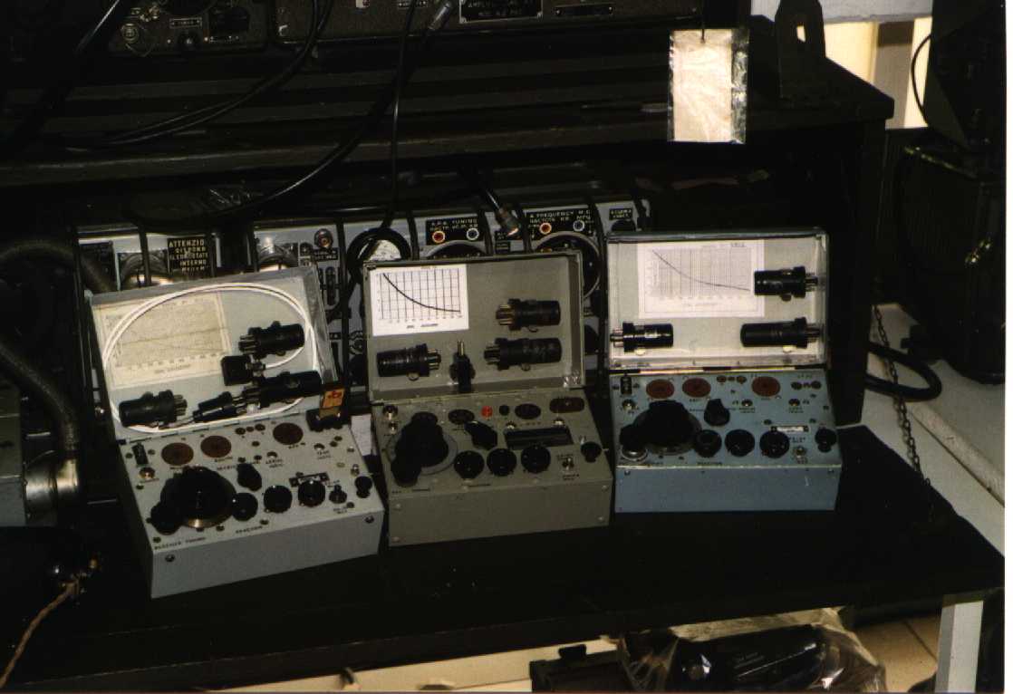
The 3 sets are completed and working. We decide
to make a meeting to match the experiences, see from the live the different
sets, test the sets. The meeting will be held on IK5FUZ's QRA. Comparing
the sets they are very similar also because the "Paraset project" has been
the first subject on our regular radio sked , and then several solutions
has been found during these QSO. We never seen an original Paraset
but comparing with the photos in our hands the sets more similar to the original
seems to be the I0BR Paraset. Infact Roberto make particular care in
the contruction of some parts like the key, the coils, and the LF impedance,
tring to replicate maximum as possible the real set.
Common comments is the good reliability of the design infact
the 3 sets also if made using surplus and home made parts worked immediately
without any problem. All the components has been tested before the assembling.
The Paraset production line.....
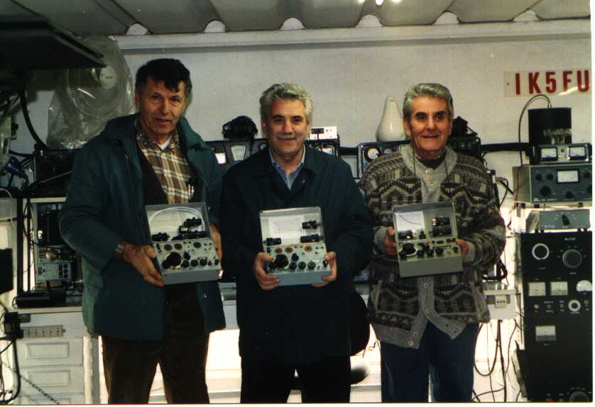
From the left : I0BR/Roberto, IK0MOZ/Mario, IK5FUZ/Alberto
--.- .-. -..-
--.- .-. -..-
IF YOU ARE INTERESTED TO THIS PROJECT, For MORE DETAIL
OR COMMENTS Send a mail to IK0MOZ