|
|
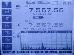
A common fault with the first model of the ICOM IC-756 series (not to be confused with the IC-756PRO and PROII) is the partial failure of the main LCD display by the appearance of a number of prominent horizontal lines (dark in my case). The lines are usually intermittent but persist. The only cure is to replace the LCD display, which in my case was supplied by the Australian Agent for ICOM. They would have undertaken the repair as well (for a price) but that would also have entailed freighting the transceiver some 3500Km with attendant cost and further risk of damage in transit.
This is an account of the process necessary to replace the display, where alternative repair facilities are not available. If anyone follows this procedure the responsibility for any damage is of course theirs.
The ICOM part number for the LCD display is:
The ICOM part number for the LCD escutcheon (cover) is:
Before starting, provide a container for all the loose screws, knobs etc that will be removed and must later be replaced! In addition, take anti-static precautions. View IC-756 Service Manual, Page 7-2.
Remove the top and bottom covers and the carrying handle.
Remove the rubber grip (it slides off) on the Main Tuning knob exposing a hole in the knob leading to an Allen key grub screw. Loosen the screw and take off the knob.
It is not necessary to remove the braking mechanism revealed under the main knob. The associated black adjusting screw (just above the "lock" button) does not prevent removal of the panel. However, the plated self-tapping screw retaining ONE END of the brake mechanism should be removed.
Remove all other panel knobs. They just pull off with a firm grip. No other controls, including the microphone connector prevent panel removal.
Now remove the front plastic panel. This is held in place by six lugs on the top and bottom edges. It is necessary to use, say, a thin-bladed knife to gently ease the plastic over the lugs while putting forward pressure on the panel. The panel is a snug fit and care must be taken to avoid any damage. The panel will not come completely away as it mounts a PCB with three short ribbon cables which attach to the "next layer" - a metal subchassis. Take care not to stress these cables at this stage.
Remove the metal subchassis behind the front panel (to which it is still attached by the three ribbon cables) from the main diecast chassis by removing the four screws (two on each side). Carefully draw the subchassis forward, limited by attached cables.
At this stage, it is possible to see that the only way to separate the component boards and panels is to remove a number of miniature ribbon cables, audio and power plugs. The miniature ribbon "header" type plugs need care but easily unplug. They use contacts moulded or plated on to the end of the ribbon cable and appear fragile. Carefully note where each plug comes from, although it is fairly difficult to make an error on reassembly (except to forget to reconnect something). Separate the plastic panel from the metal sub chassis by disconnecting its three cables.
To remove the LCD itself, it is necessary to remove the sub-logic board which is mounted on the metal sub chassis. Remove the securing self tapping mounting screws from the board and all cable connectors.It is necessary to undo the mounting nuts on the AF/RF pot and the BAL/NR pot. It is also necessary to unsolder the two connections to the S meter (marked with two white arrows on the board) and withdraw the S-meter forwards. Note that the meter movement is unprotected once the plastic front panel is removed; avoid damaging the meter pointer and movement while working on the panels. Stow the meter in a safe place.
Note that one ribbon cable connects the LCD to the main chassis and this cannot be unplugged until the sub logic board is removed, so take care not to strain or damage this cable in the process. It could be a good idea to locate the other end of this ribbon on the main chassis and unplug it there so giving more freedom of movement.
Carefully remove the sub-logic board. Now the LCD itself is exposed and can be removed. It is held by two screws and two detents. There is one power plug and one ribbon cable. The ribbon cable is further restrained lightly by a strip of self adhesive reinforced packing tape. This latter cable is the one that connects to the main chassis as in (9). Remove the cables and the adhesive strip and the LCD and its attached board.
The LCD is fitted with a separate black anodized escutcheon which is a separate ICOM part number (refer to PARTS REQUIRED above). When ordering the LCD, it is recommended that a new escutcheon also be ordered to go with the new display. I did not realize this and was obliged to try and salvage the old escutcheon. This was possible - just, as the escutcheon was originally attached to the old LCD with some sort of strong adhesive. A knife with a thin long blade was used in this case to prize off the escutcheon. It is easily possible to damage the part beyond repair so be careful if you must re-use the old one.
(Contributed by Adam Maurer, VK4CP). Note that the escutcheon is asymmetrical; the left edge of the black surround is 1-2mm wider than the right edge. This became apparent when I reassembled the radio (before fitting the front panel) and powered it up, to check the new display. I noticed a blue edge on the left edge of the LCD, and the right edge was cropped. The escutcheon was easy to pull off again (not requiring full disassembly), and stick down again, the other way around.
Proceed to re-assemble in the reverse order, starting with the LCD, taking particular care to correctly re-seat the ribbon cables, and not forgetting to re-solder the S-meter in place. The escutcheon can be refitted once the LCD is screwed into place. Don't forget to replace the adhesive tape re-inforcing the cable from the main chassis to the LCD board, or the nuts from the AF/RF and NR/BAL controls. The plastic front panel just clicks into place over its six lugs.
On switching on, no problems were encountered that required re-setting of the CPU. All memory data was unaffected. However the time display did show 00.00 and counting, so had to be reset to the correct time from the menu. (See users manual). The lithium battery for the clock is mounted on the front panel and is obviously disconnected via one of the cables removed during the dismantling.
Some of the processes are awkward because of the limited length of the ribbon cables, but are achievable. There may be a better way to go about the repair but these notes are provided to assist those who have wondered if it is a feasible "do-it-yourself" exercise.
At first inspection it seems that one can avoid the need to remove the plastic front panel thus saving a deal of effort. However the critical path in this exercise is the unavoidable need to undo the mounting nuts for the AF/RF gain and NR/BAL control so that the sub-logic board can be removed to get at the LCD. This cannot be done with the front panel in place - unfortunately.
An IC-756 service manual is available at mods.dk, and is always a useful aid. However it is not really essential as it contains little more than board layouts, circuit diagrams and parts lists. The most useful section for this exercise is perhaps the one containing "exploded" mechanical views (Page 7-2). It does not tell one how to get everything apart, however. Click here for Page 7-2, and download DC-DC converter information (courtesy Icom Inc.) Read an excellent article on the CCFL backlight lamp.
Note by Adam, VA7OJ/AB4OJ: Dick Knol, PA3DUV, was able to obtain a replacement LCD display module via Icom UK several years ago. The new module was manufactured in Taiwan. View photos of the old and new display modules.
A. Farson VA7OJ/AB4OJ edited Don's original text, and created this page.
Last updated: 07/12/2009
![]()