 |
On the issue of replacing the plastic VCO trimmers, I use the 6 pF "Red" ceramic trimmers for C97 and C107 in the two higher-frequency VCO's (the two closest to the rear of the radio) and 12 pF "White" ceramic trimmers for C78 and C88 in the two lower-frequency VCO's (the two closest to the front). I have always had very good results with these values, and they are available from ICOM America for about $1.65 each, as I recall.
Part numbers for the ceramic replacement trimmers supplied by ICOM are as follows:
These part numbers are applicable for all the ICOM rigs that use the (4) VCO trimmer capacitors, such as the R-71A, IC-751/A, IC-735, etc. ICOM also carries a 24 pF NP0 ceramic disk capacitor that is perfect for the IC-745 2nd LO Unit Stability Upgrade. Its Icom part number is:
 |
When removing the lower VCO shield to replace the trimmers, be very careful regarding the amount of heat used to remove the shield. The rectangular PCB pads that the shield tabs are soldered to are pretty stout, but will delaminate from the PCB if overheated. Also be very careful not to inflict collateral damage, as there are some component leads that will be heated during this process. Be careful not to overheat these and damage the components.
When re-soldering the lower shield, exercise care so as not to form any solder bridges under the shield, these can be hard to see.
When installing the VCO trimmers, ensure that the rotor of the trimmer is connected to ground. You probably will notice a silk- screened trimmer outline that would have you install the trimmer backwards. Ignore that, and install them with the rotors grounded. This will make tuning much, much easier.
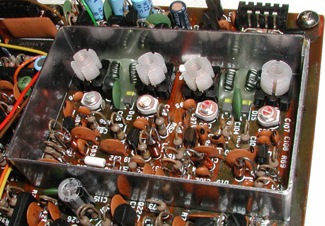
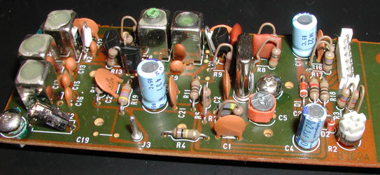
Fig. 2 (above) shows the 745 VCO box after trimmer installation, and prior to additional beeswax being added. Note the small amount of factory beeswax around the inductors at the top of the picture. Note that C107 (the highest-frequency VCO) is to the right. Also note the orientation of the trimmers; the profile of the trimmers is 180º out from the silk-screened profile on the PCB. This is the correct method, and places the trimmer rotors at ground.
When aligning the PLL VCO's after updating the VCO trimmers in the IC-745, you should pay attention to the "PLL Lock Voltage". The IC-745 Service Manual has you "verify" this voltage during the alignment, as it is not adjustable.
Comparing the IC-745 vs. IC-751A PLL designs, and their respective alignment procedures, I am convinced that the "HPL Lock Voltage" value (adjustable in the IC-751A via R43) should be the same as that shown in the IC-745 "PLL Lock Voltage" verification step. When doing the IC-745 I trim the fixed value of R43 by hand to put the lock voltage in the center of the IC-751A's allowed tolerance.
This voltage is typically found to be near the low edge of the limit, but still in spec. R43 controls the value of the PLL Lock voltage (termed HPL Lock Voltage, and adjustable, in the IC-751A.) Again, the PLL Unit is essentially the same as the PLL Unit in the IC-751A. You will see the mounting location for R43 next to the VCO box; it is designed to accommodate a potentiometer. In fact, a potentiometer is used in the IC-751A, and is part of the alignment process.
In the IC-745 you will find a fixed resistor instead of the pot. That is OK, as I usually replace the pot in the IC-751A with a fixed film resistor anyway. This pot can get noisy, and will affect all VCO ranges - not just one or two like a trimmer. The design value for R43 in the IC-745 is 1.2K, but this value is a little high. I have found that reducing the value of R43 to 1.1K, 1.0K, or even 910 ohms is much better.
I typically align the IC-745 PLL, then note the PLL Lock Voltage reading. If the PLL Lock Voltage is near the low edge of the spec, I will hand-select one of the above values (1K usually works just fine, but on some radios I have taken it down to 910 ohms) to place the PLL Lock voltage closer to the center of its spec. This change will add stability to the PLL and decrease the PLL lockup time after a frequency change. Make sure you use a good quality metal-film resistor for R43, as any noise here will "contaminate" the VCO output.
It may seem from the above that I was saying there are numerous 2nd LO alignment steps. Actually, there are only two alignment settings, with a couple more steps to perform as a verification. It is actually much easier to do it than to describe how to do it. Obviously, a lot of the information presented can be applied to other ICOM radios as well, especially as regards the VCO Trimmer replacement.
The IC-751A PLL alignment procedure is also valid for the IC-745. Download it here (PDF).
 |
While on the topic of the 745's PLL, here's some more info. The 745's VCO is somewhat microphonic. That is to say, the PLL loop gain is so high that any vibration imparted on the VCO will FM the VCO output, and you can hear it.
If you want to observe this first-hand, tune the radio to a carrier, or simply use a signal generator to provide perhaps an S-5 or so signal to the 745. Tap on the VCO box and you will be able to hear the tapping sound "modulating" the received tone from the speaker. This is VCO FM'ing and the only way to cure it is to dampen the vibration in the VCO box itself.
In later rigs such as the IC-751A, beeswax was added to certain areas of the VCO box to help eliminate microphonics. This application of beeswax has been incorrectly blamed by many for the notorious VCO Trimmer problem, the explanation being that the beeswax contaminated the trimmers. Wouldn't beeswax contaminate ceramic trimmers, too? The 745's VCO box never used beeswax, so that theory is pretty much a sham. (Note by Adam VA7OJ/AB4OJ: Actually, metal migration over time causes the plastic VCO trimmers to fail.)
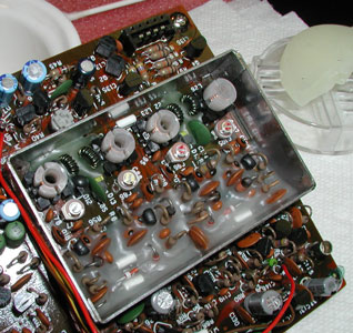
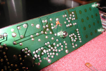
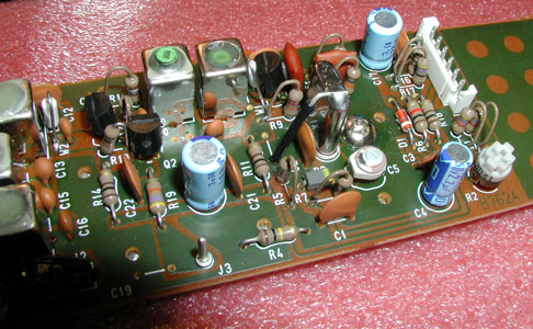
I recommend carefully sealing the 745 VCO components with beeswax. Fig. 3 (above) shows the 745 VCO box after beeswax is added. This closely resembles the "factory" IC-751A VCO box beeswax staking method.
Do not use paraffin; it has a higher melting point and will subject the FET and diodes in the VCO circuit to high heat stress. Also, use a little at a time and build it up in layers, to avoid high heat stress to the semiconductors. Be very careful not to get any of the wax near the new ceramic trimmers; the wax will certainly foul them. And don't overdo it - if the components are half-covered that's enough, although I usually add a bit more.
This beeswax VCO sealing procedure is optional, and if you don't want to undertake such a job, don't. The radio is pretty good as it is, and this suggestion is simply an incremental improvement, not a "make-or-break" mod.
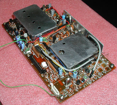 |
Fig. 4 shows the Reference Oscillator area of the 745 PLL Unit, at the right front corner of the board (bottom of photo). Note the "missing" component locations to the right of the Reference Oscillator crystal. In the IC-751A these parts are populated and form a doubler, which generates the 61.4400 MHz 2nd LO signal.
Since these components are not present in the IC-745, a separate "2nd LO Unit" with its own crystal is installed to generate this signal.
 |
Figs. 5 and 6 show the IC-745 2nd LO Unit before the upgrade. The 24 pF NP0 ceramic disk capacitor which is to be installed is visible in Fig. 6.
 |
If you intend to replace the plastic 30 pF "Orange" trimmer in the 2nd LO Unit, you might as well go the whole nine yards and do the Stability Upgrade too. The IC-745's 2nd LO Unit has a frequency stability issue that is primarily due to the crystal's frequency-trimming design. The ICOM design uses a fixed 6 pF disk ceramic capacitor in parallel with the 30 pF trimmer to adjust the 2nd LO frequency. This ratio is unbalanced and should be reworked so that the majority of the total crystal trimming capacitance is fixed, not variable.
The "2nd LO Stability Upgrade" is accomplished by installing a 12 pF "White" ceramic trimmer in place of the huge 30 pF "Orange" trimmer, and installing a 24 pF NP0 disk on the solder side of the board, in place of the old 6 pF disk. After the upgrade, you will still have 36 pF of total trimming capacitance, but the largest part of it will now have a much lower temperature coefficient.
While performing this upgrade, carefully bond the crystal case to ground. This will add to the overall stability of the circuit. There is a conveniently located and unused hole in the PCB near the crystal, that carries through to the ground plane of the PCB and is a perfect place to add a ground jumper. Be careful, though, as there are two unused holes very close together, and only one of them is ground. I normally add a small length of 22 AWG tinned buss wire between this ground point and the top of the crystal can. Be careful when soldering the buss wire to the crystal, to avoid overheating and damaging the crystal.
Fig. 7 shows the front of the 2nd LO Unit after the upgrade. Note the new ceramic trimmer, and the crystal bonding strap.
 |
You will find that this upgrade greatly reduces the frequency drift of the IC-745, especially if an internal power supply (IC-PS35) is installed. The edge of the PS-35 case is right next to the 2nd LO Unit when it is installed, and greatly magnifies the design weakness of the 2nd LO Unit.
Others have reported also cutting out a small styrofoam block, then coring it out and slipping it over the crystal can to further enhance stability. I have never found this necessary, though. One note of caution, however. After soldering the bonding strap to the crystal can, allow plenty of time for the crystal to return to ambient temperature prior to alignment, or you will be just wasting your time.
There is a caveat regarding the alignment of the 745's 2nd LO Unit, because it is a little different from most. During alignment, you have to basically adjust the 2nd LO frequency as follows:
Adjust in receive with no RIT
Adjust in receive with RIT on and centered
Verify in transmit with no XIT
The design is somewhat bizarre, in that you can actually have a "split" between transmit and receive, with no RIT and no XIT applied. Be careful of this, especially if planning on using the radio for PSK-31. During most "normal" alignments, getting it within 10 to 20 Hz is more than enough. When using PSK programs with "AFC" turned on, a split of more than 10 Hz or so will cause you and the station you are in QSO with to slowly chase each other up (or down) the band, just as if RIT was on.
The other digital modes will easily tolerate a 10 Hz or greater alignment split, but because PSK-31 is only 31 Hz wide, 10 Hz is one-third of your transmitted occupied bandwidth. When aligning the IC-745's 2nd LO, be mindful of this if you plan to use the radio for PSK-31.
Try to get the 2nd LO frequency as close to 61.4400 MHz as possible in all the separate alignment steps, but be aware that the critical parameter is the amount of split between "No RIT Rx" and "No XIT Tx", not the absolute frequency accuracy. If you don't plan to use PSK-31, 10 - 20 Hz on all alignment steps is more than enough.
RIT/XIT Switches and pots are a major problem in the older ICOM radios. The 2nd LO Unit in the IC-745 is where RIT, XIT, and Calibrator offset voltages are applied. The circuit is very sensitive to changes in the trimming voltages. Very slight changes in the applied voltage will cause audible frequency pulling.
Part of the problem is that the switches and pots have metallic housings. Dirty switch contacts are well-understood, but cross-conduction between the internal switch structures and the metal case will also cause very small voltage changes which pull the oscillator.
I strongly discourage using "Blue Shower" as suggested by ICOM. This "contact cleaner" leaves behind a heavy, oily residue that will contribute to the internal cross-conduction in pots and switches and will soon compound the problem. I prefer to clean the RIT/XIT pots and switches with a zero-residue cleaning substance.
Freon TF is excellent, but is very hard to find. Trichloroethane is also excellent, but may be difficult to find, or expensive. For day-to-day jobs at home I normally use 100% isopropanol (anhydrous "rubbing" alcohol) and not the drugstore variety, which may contain up to 30% water.
I inject the alcohol into the control with a small syringe. The control can then be operated repeatedly, and most of the solvent will evaporate. Canned compressed air can be applied via a wand to completely dry out the remaining alcohol. Isopropanol does not attack most plastics as some other solvents will, but it is always prudent to watch overspray and protect the surrounding plastic items so as to be sure.
That's about it for now, I hope this information will be helpful. Enjoy your IC-745; it is a true ICOM Classic. I love mine! Good luck, take your time, and update your radio with a little work, and also pick up some new skills along the way!
73, Frank W3UHF
A. Farson VA7OJ/AB4OJ edited Frank's original text and created this page.
Last updated: 08/28/2016
![]()