The problem manifests itself as birdies, or a “warbling” sound in the receiver.
When powered up, the IC-2KL produces very noticeable birdies about every 10 kHz, over the entire HF range from 80m to 10m. The frequency of the birdies is not constant. When the amplifier is first turned on, they are drifting very rapidly; as the amplifier warms up, the drifting slows (but never stops). If the receiver is sitting on a set frequency, the birdies "drift by" about every 5 to 30 seconds (depending on how long the amplifier has been on). When tuning across a band, birdies can be observed at intervals of approx. 10 kHz. The birdies are about S2 on 10 meters, and are thus very disturbing. They are visible on the IC-756Pro or IC-756Pro II spectrum scope. The birdies often sound like a warbling tone, similar to the sounds that sunspots emit on the HF bands.
The birdies occur whether the LINEAR switch on the IC-2KL is ON (operate) or OFF (standby).
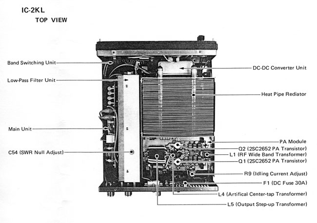
The problem is probably caused by a parasitic oscillation in the DC-DC converter unit inside the RF cabinet of the IC-2KL. The converter module is in a small, shielded enclosure on top of the chassis, behind the meter. (Refer to Figure 1, IC-2KL Top View).
This converter changes the 40V DC supply to ± 13.8V for the control and protection circuits. The easiest way to verify this is to disconnect the +40V input to the converter and verify that the birdies cease.
 |
Check the connections and grounding of the converter. Loosening, and then re-tightening, the mounting screws (also those inside the converter enclosure) may help reduce the birdies. Cleaning the mating surfaces of the enclosure and cover may also help. It may be necessary to replace some electrolytic filter and bypass capacitors in the DC-DC converter. (Refer to Figure 2, DC-DC Schematic).
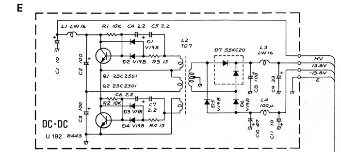 |
Replace the electrolytic capacitors C8, C9, C10 and C11. Add three 100 nF (0.1µF) 50V ceramic disc capacitors as shown in Figure 3 (below). This should completely eliminate the problem.
 |
These tuners incorporate a DC-DC converter similar in design to the one in the IC-2KL. This converter can also cause birdies, and the cure is as described for the IC-2KL.
 |
I have "thrashed" my IC-2KL trying to clean up the mess and got a good bit of it quieted down, but there is still some left. Here is what I have tried so far:
Installed 1000 pF feedthrough capacitors on all wires coming out of the box (even the ground wire), this made a minimal improvement (Figure 3 shows the feedthrough installation. The ground wire has been extended and is now on the opposite side of case, not with the power wires).
Installed RF bypassing (1000 pF and 10µF) on the PCB for the input and output power leads (some improvement). Some of the additional bypassing I did was in the form of chip caps. I found a few areas where a voltage rail was near a ground, so I simply removed the solder mask with an Exacto blade and laid down the chip directly across both traces.
Replaced both switching transistors (moderate improvement). I am convinced that matched transistors and/or independent adjustment of their bias, or even balancing the transformer windings to achieve better switching crossover is the key.
Replaced rectifier diodes and filter capacitors - some improvement.
Temporarily installed ferrites on all leads - no improvement. Large amounts of inductance may help, but to be effective they may have to be inside the box, and this is not practical. Also, this would not address the real issue anyway. I eliminated at least half the noise, and the remaining noise level seems to diminish as the unit warms up! Perhaps the switching transistors are better balanced (in my case) when hot.
Supporting the possibility of a parasitic is the fact that if one applies pressure to the lid of the DC-DC, there seems to be a slight "characteristic" change. I feel that it is transformer-related (even though the lid is aluminum!) rather than a capacitive effect to another circuit element on the PCB. Just a gut feeling though.
One might also try using different values of capacitors in the circuit to see if the characteristics of the suspected parasitic can be made to change. I have a deep dark fear that the LC combination responsible for this parasitic, if it is indeed one, may be inherent in the transformer's construction.
- Frank A. Ellis, W3UHF September 25, 2002
Comments on the above by Adam, VA7OJ: Did you ever try to slip ferrite beads over the base leads of Q1 and Q2 in the converter box? Also, if a particular LC combination involving the transformer primary is the cause, a small capacitor across the primary may make a big difference to the frequency or rep rate of the spur.
Add a 1A fuse in the 40VDC line from the main PS to the DC-DC converter. This will prevent more costly damage to the main PS if the DC-DC converter blows up. The converter costs only $30 (if you can still find one at Icom Parts.)
Change the cooling-fan activation mode. The heat sink temperature has to be 50ºC or higher, AND the transceiver must be in transmit mode, in order for the fan to come on. A simple wiring change will allow the fan to run with device temperature > 50ºC, even when not transmitting. The roar of the fan is another issue, though...
- Frank A. Ellis, W3UHF
View an IC-751 DC-DC Converter EMC Mod (PDF)
Copyright © 2002 A. Farson VA7OJ/AB4OJ. All rights reserved. Figs. 1 & 2 courtesy Icom Inc. Fig. 3 courtesy W3UHF.
Last updated: 06/09/2006
![]()