Due to a big thunder storm, the second part of
Stacking Antennas article became a reality. In fact due to this
storm a twin of my TH5, badly fell on Parma's roofs, became
available. Being in a very bad conditions, it took quite a bit of
work to put it back on the air, but it worth the job.
To get to the point, at the end of the previous article we sad we
were going to look at the topic in a more practical manner, as
making the match transformer, the switching box and so forth.
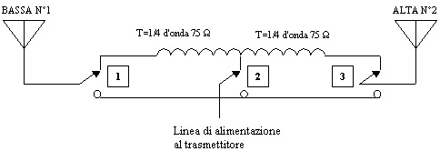
The usual way to match two antennas in phase place within the same axis is by means of a transformer made of 75 ohms coaxial cable. If the stack must be selectable, the quarter wave sections need to be removed.
RELAY |
BOTH N°1, 2 |
LOWER N°1 |
UPPER N°2 |
1 |
OFF |
ON |
OFF |
2 |
OFF |
ON |
ON |
3 |
OFF |
OFF |
ON |
In case the antennas individual switching is
not a must and only a single band is required, this system is
very handy and quick to make. If vice versa the idea is to match
two tribanders, it is not suitable since can only be used on the
band related to the quarter wave of the 75 ohms coaxial cable,
even more if the option is to switch the antennas one by one or
both.
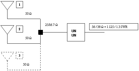
The so called UNUN is a broad band unbalance transformer. The
main characteristic are: small dimensions which allow switching
relais to be placed within the same moderate dimensions matching
box. This method does not require a precise coax cable cut of
given dimensions.
The only requirement is the exact length of the coax cables going
to the antennas, preferably different from a quarter wave length
and multiple odds to avoid unwanted matches (multiband antennas
are not exactly 50 ohms on each band).
Being the UNUN match ratio constant across a wide frequency
range, it becomes possible to easily match ether monobander , log
periodic, cubic, tribander, etc.
You do not need to be a Big gun to take advantages from a beams
HF Stack, this is probably one of the most efficient upgrade you
can add to your contest station, in stead of just buying a linear
amplifier, which offers very little benefit on RX.
If the antennas rotates independently, you can also receive and
transmit in two different directions simultaneously.
The idea for my BOX came from the "STACK
MATCHER" of WX0B, which allows to feed two or three antennas
with a single transformer.
In stead of making one "UNUN" with 3:1 ratio to feed
all three antennas or one with 2:1 ratio for two antennas, Jay
came out with a ratio of 2.25:1 which is a compromise absolutely
acceptable.
A "UNUN" transformer 2.25:1 ratio is very simple to
build, does not require intermediate taps and can be build to
handle enough power.
When is used to match two or three antennas sufficiently spaced,
the SWR dip keeps almost the same frequency as per the single
antenna alone (it should actually enlarge, NDR).
Personally, on 10M the 1:1 ratio was slightly lower from the
single antennas alone.
All you have to do is to place the UNUN in a water proof box , better if put half a way from the two antennas (less cable), and feed these last with identical 50 ohms coaxial cable lengths.
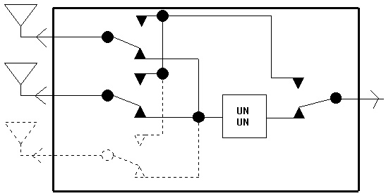
By putting the selection relais within the same UNUN box, by
means of a remote cable, it is possible switch from the shack
among the three possible combinations.
A simple two or three position rotary switch, wired properly, is
probably the most practical solution.
With all the antennas fed, relais are not energized (OFF),
transformer on the line (through), as you select every single
antenna, the relay which by-pass the transformer comes ON (transformer
off line) as well as the specific one for the antenna selected.
To save a wire, when a specific relay (upper or
lower antenna selected) is ON, it is possible by means of a diode
to turn ON also the common one.
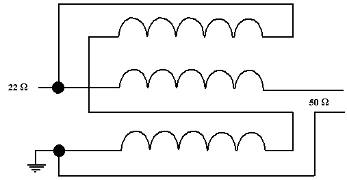
The way to build the UNUN transformer, consist
in winding on a toroid with permeability of 125 or less (for a
near 100% efficiency at HF frequency) 5 wraps of trifilar
enamelled copper wire.
The wire diameter depends on the handled power (in my case 1,5 mm),
fold the tips in order to make connections as shown in the
picture
Always check the unit on 25 or 16,7 ohms dummy
load, made by putting in parallel two or three 50 ohms dummy
loads connected to the output of the unit.
For my test I used the MFJ antenna analizer (thanks to I4WMG) as
a generator, and two or three anti-inductive 47 ohms 1/4 Watt
resistors in parallel.
With dummy load properly dimensioned, you may use your RTX at the
minimum usable power to read the SWR.
The stack works very well indeed, and is easy to find it out ,
simply switch between the possible combinations, it also allows
you to understand the various propagation modes.
Furthermore, the possibility to transmit and receive
simultaneously from two different directions is an extra card to
play and not to underestimate in order to fully maximize all the
operative capability.
See you in the contest, I4LEC