
10G2 DB6NT Transverter per 10368 MHz
10G2 DB6NT Transverter for 10368 MHz
(year 2016)
|
|
photo gallery
![]() Cliccare sulla foto per vedere la massima grandezza con
la miglior qualità
Cliccare sulla foto per vedere la massima grandezza con
la miglior qualità
![]() Click
on a picture to view it full size with full quality
Click
on a picture to view it full size with full quality
|
|
|
|
|
|
|
|
|
|
|
|
![]()
![]() Transverter per 10 GHz (versione 2016)
Transverter per 10 GHz (versione 2016)
![]()
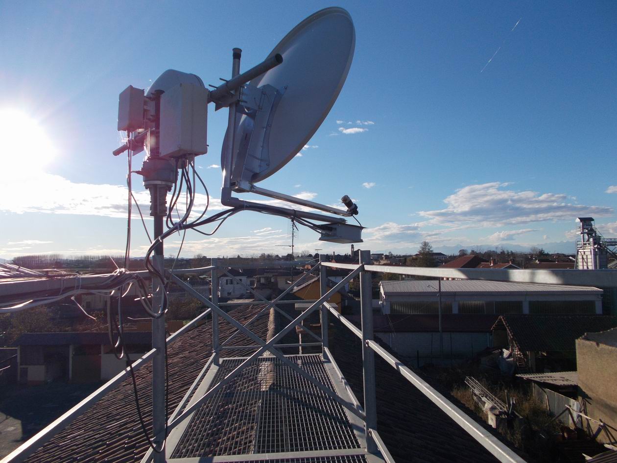
Per migliorare ulteriormente le prestazioni del mio setup in 10 GHz ho pensato
di fare delle migliorie: passaggio dagli attuali 4 W di uscita a 8 W e
sostituzione della parabola 80 cm offset con una da 1 metro sempre offset.
Il mio nuovo transverter per i 3 cm è quindi così composto:
XVTR MKU 10G2, PA da 4 W, PA da 8 W, Oscillatore Locale a 106.500 MHz pilotato
da un sintetizzatore con ingresso a 10 MHz da Oven, convertitore di tensione (12
> 24 Volt) per il relè coassiale d'antenna, LNA ricavato modificando un modulo
per la ricezione TV Sat tipo SU-02 e, infine, un sequencer.
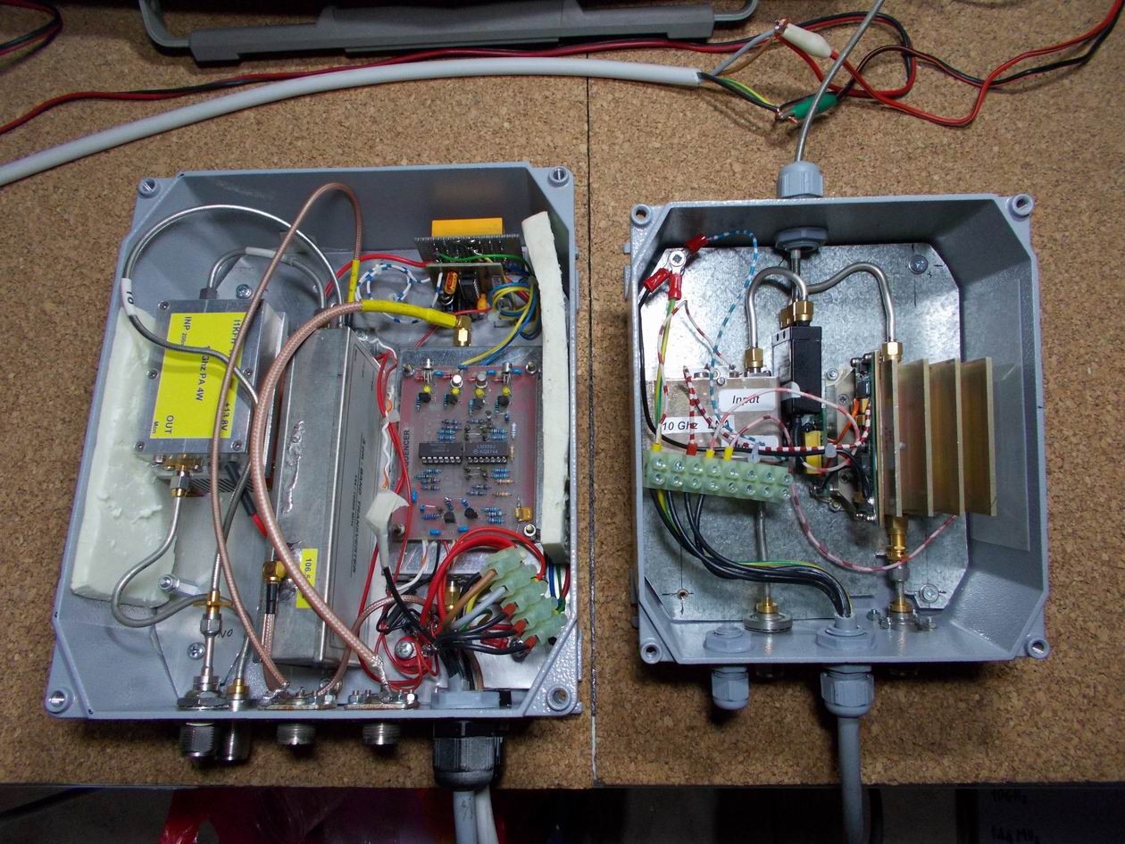
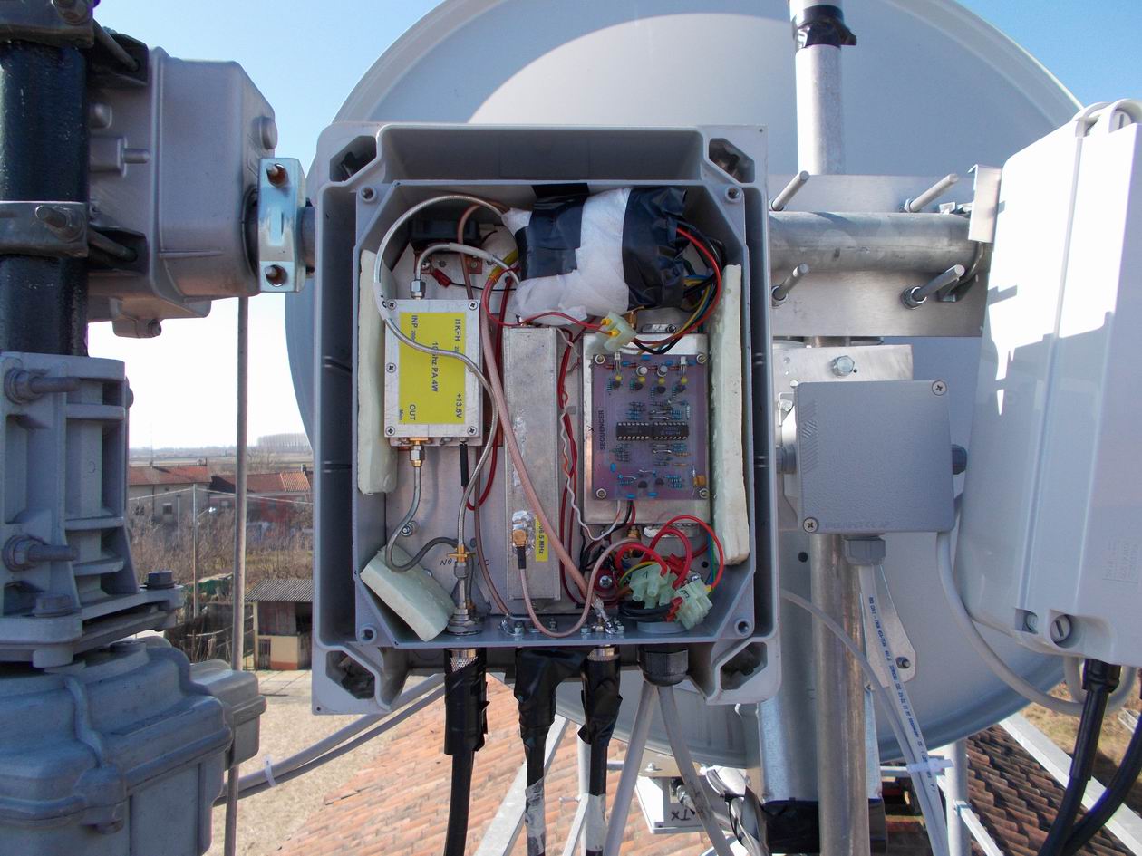
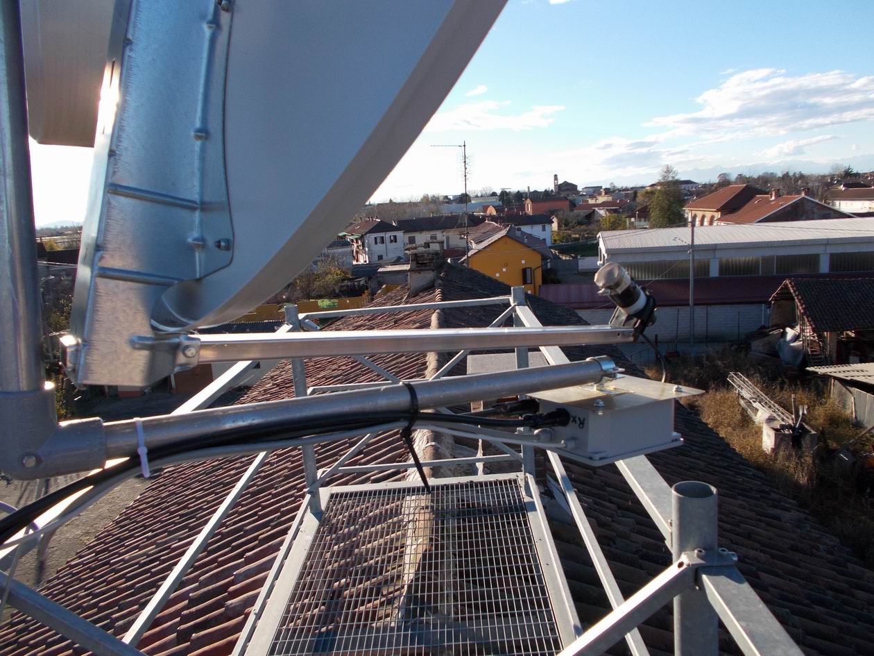
Per minimizzare le perdite ho deciso di usare due contenitori di alluminio per
l’assemblaggio: in uno (il più vicino possibile all’illuminatore) si trova il PA
da 8 W, l’LNA e il relè coassiale. Nel secondo invece abbiamo il MKU 10G2, il PA
da 4 W, l’OL, il convertitore 12 >24V e il sequencer.
![]()
E' sicuramente il
più famoso, il più ambito e il più performante transverter dell'ultima
generazione per la banda dei 3 cm. Si trova in kit o già montato e collaudato.
Personalmente preferisco la versione in kit perché, oltre alla differenza di
costo, c'è la soddisfazione di averlo assemblato con le proprie mani. E' una
costruzione molta compatta e con componenti SMD, ed è necessaria una certa
esperienza per il montaggio. Il manuale di costruzione spiega di montare prima
tutti i componenti e poi passare alla fase di taratura che si effettua tramite
un normale tester.
Personalmente non ho seguito alla lettere le istruzioni di montaggio, ma ho
preferito installare i componenti per stadi:
1°- la parte di alimentazione e il suo collaudo
2°- l'oscillatore locale e la taratura della frequenza con il controllato della
stabilità
3°- lo stadio RX e taratura
4°- lo stadio TX.e taratura
Traduzione in Italiano delle parti principali del manuale del kit MKU 10G2
![]()
L'oscillatore
locale è a 106.500 MHz e per avere una buona stabilità di frequenza ho pensato
di utilizzare il Sintetizzatore progettato da F9HX/F5CAU.
Il progetto si può trovare sempre su questo sito alla dicitura
'106.500 MHz Local Oscillator controlled by GPSDO'
Purtroppo il sistema con il GPS era instabile senza capire il motivo. A questo
punto ho usato un oven a 10 MHz in sostituzione del GPS e i risultati sono stati
molto soddisfacenti.
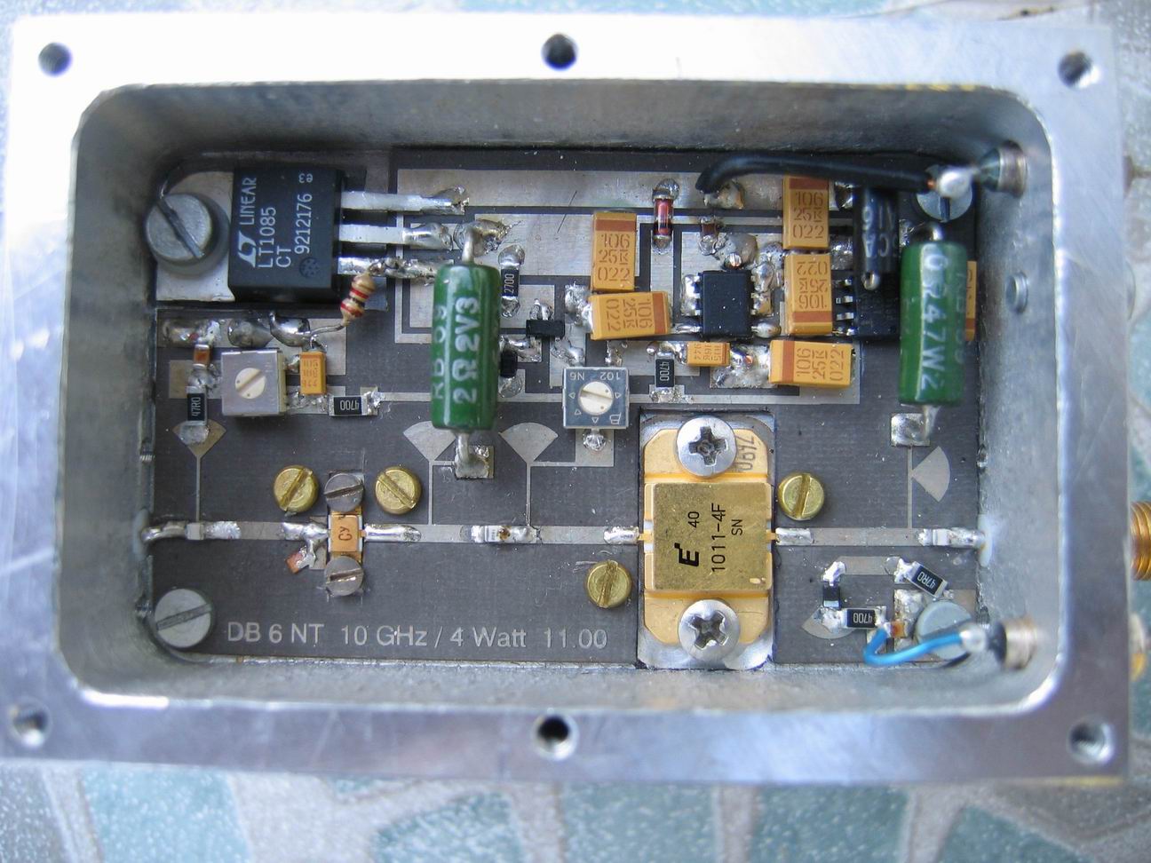
![]() Il PA
da 4 Watt
Il PA
da 4 Watt
Da tempo avevo intenzione di incrementare la potenza di uscita del mio
transverter per i 10GHz: passare da 1 a 4 Watt. Ero però frenato dal costo
smisurato del GaAs Fet utilizzato come PA. Alcuni anni fa però comparvero sulle
bancarelle dei mercatini radioamatoriali dei power GaAs Fet ad un costo più
abbordabile. Era il tipo TIM1011-4L e suo relativo driver.
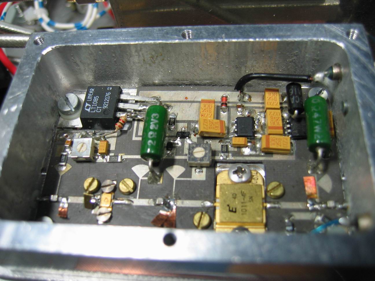
Spinti da IZ1EVF Piero, che aveva già in precedenza costruito un PA da 4 W
utilizzando questo GaAs Fet , io e I1GPE Beppe ne comprammo un paio a testa.
I circuiti stampati li acquistammo direttamente da DB6NT, Beppe costruì gli
scatolini fresati per alloggiare il PA. I1GPE lo costruì per primo ed il
risultato fu veramente soddisfacente.
Poco tempo dopo anch'io lo costruì però ebbi difficoltà nella taratura, o meglio
nella 'spagliettatura'. Il mio PA lo portai a Beppe che con la sua
esperienza e, sopratutto, pazienza riuscì a tararlo.
 |
 |
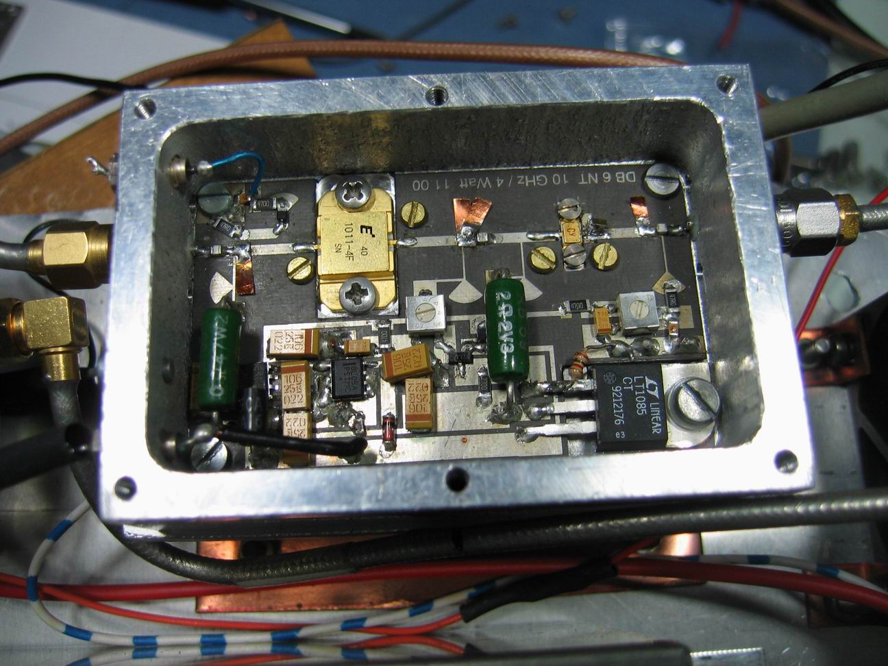 |
![]()
Questo PA è stato costruito da Piero IZ1EVF.
![]() Il
preamplificatore
Il
preamplificatore
Si tratta di una
piastra amplificatore low-noise mod. SU-02. Questa piastra è un doppio
amplificatore a 4 stadi su laminato in teflon, utilizzata originariamente come
stadio front-end low-noise per la ricezione TV Sat a 11 GHz. La cifra di rumore
attenuta è di circa 1 dB.
Le informazioni
dettagliate comunque si possono trovare su http://www.rf-microwave.com/datasheets/4_generic_SU-02_01.pdf
La piastra mod. SU-02 è in vendita da Franco Rota http://www.rf-microwave.com/
al costo di 3-4 Euro l'una.
Interessante l'applicazione di IZ4BEH Roberto al link
http://www.iz4beh.net/pre3cm.htm
Quella utilizzata è stata modificata da Piero IZ1EVF.
![]() Il
sequencer
Il
sequencer
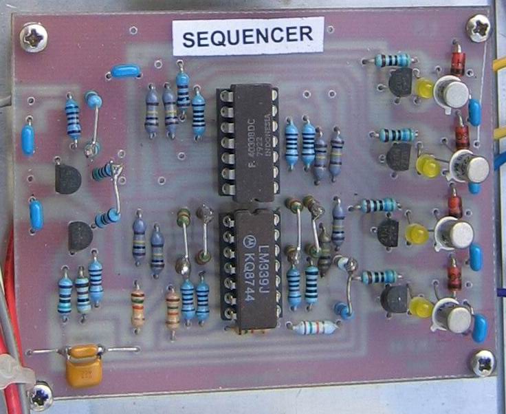
![]()
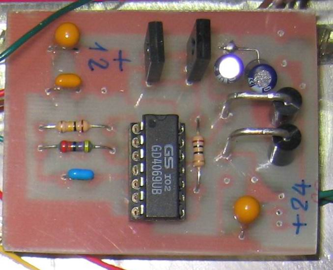
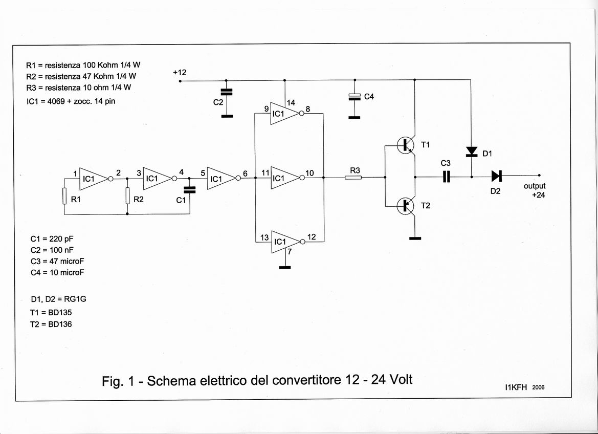
Questo dispositivo serve per alimentare il relè coassiale che funziona a 24 V.
Schema elettrico
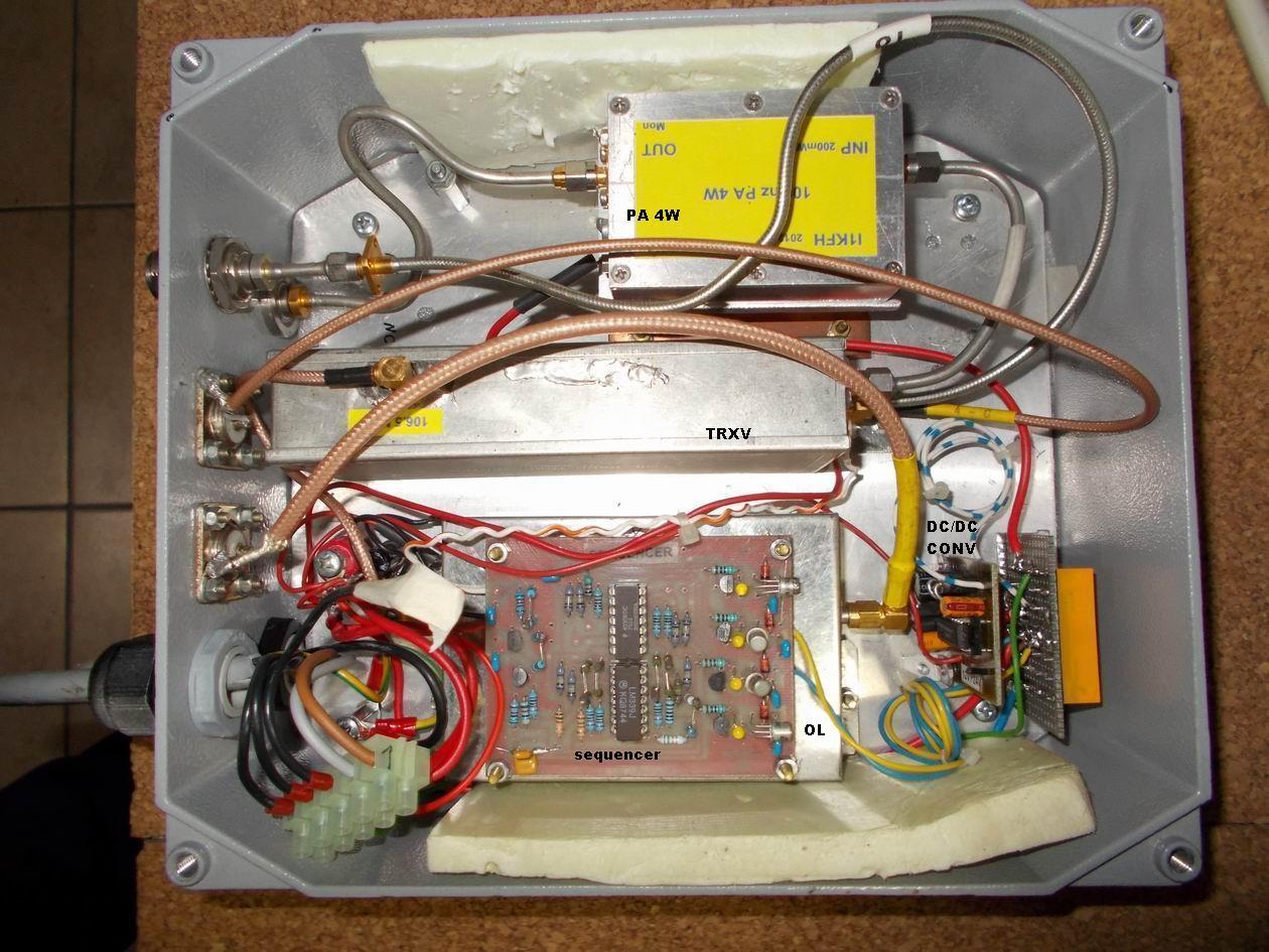
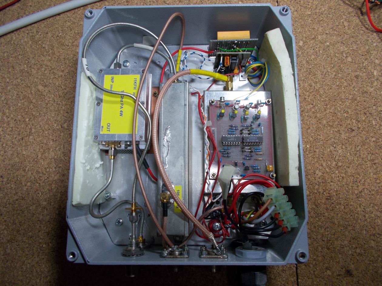
![]()
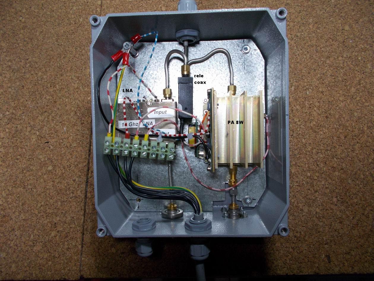
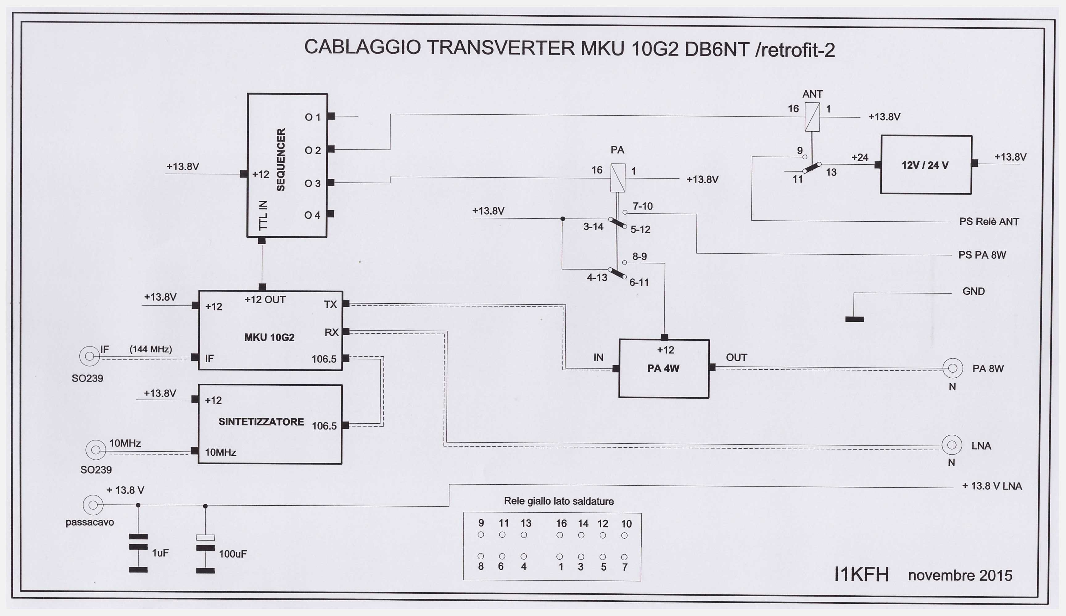
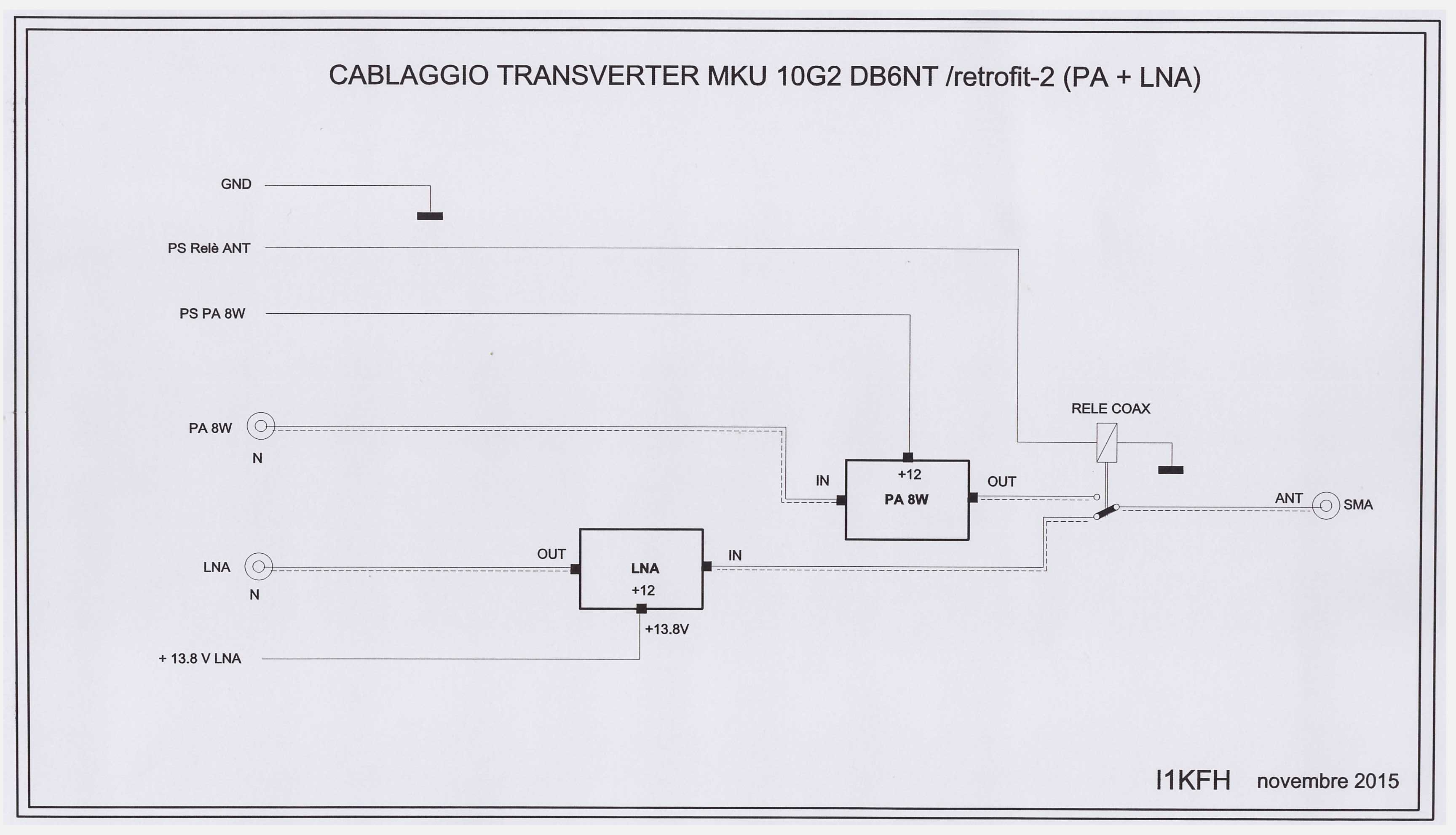
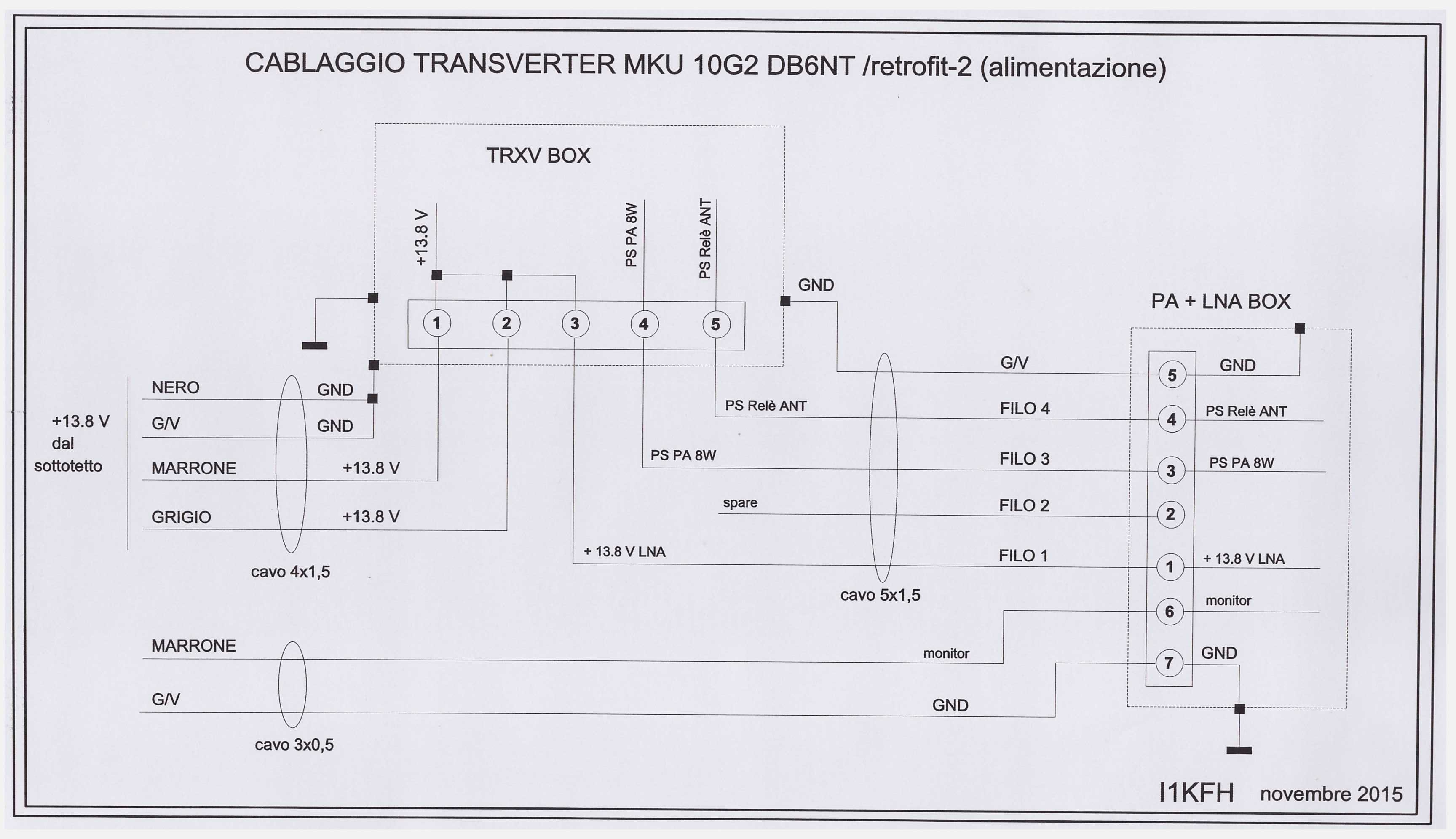
Per minimizzare le perdite ho deciso di usare due
contenitori di alluminio per l’assemblaggio: in uno (chiamato PA+LNA BOX e il
più vicino possibile all’illuminatore) si trova il PA da 8 W, l’LNA e il relè
coassiale. Nel secondo (chiamato TRXV BOX) abbiamo il MKU 10G2, il PA da 4 W, l’OL,
il convertitore 12>24V e il sequencer.
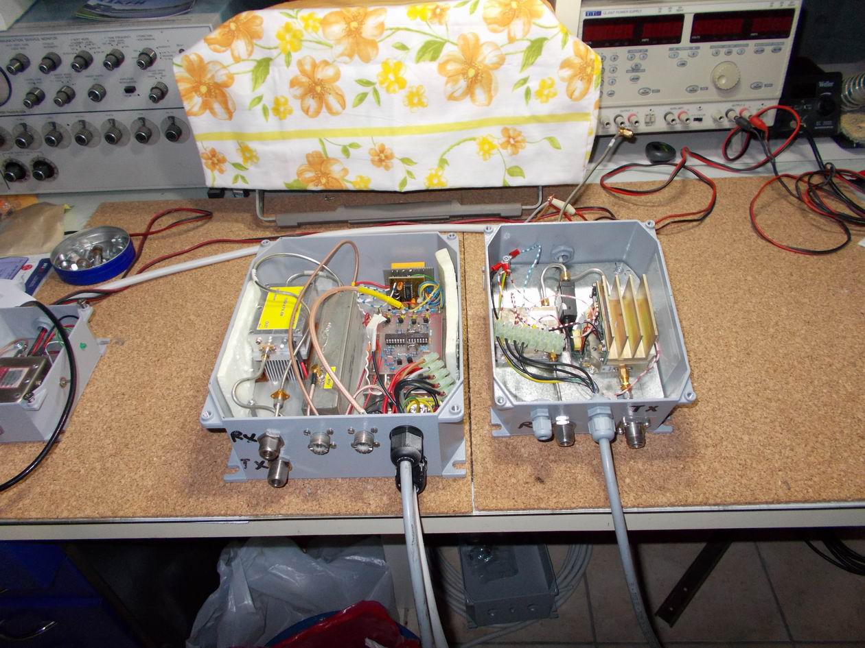
I segnali RF a 10 GHz (RX e TX) tra i due contenitori viaggiano su del cavo
Aircom Plus. Un cavo multiplo porta l’alimentazione all’LNA, al PA e il comando
al relè coassiale d’antenna.
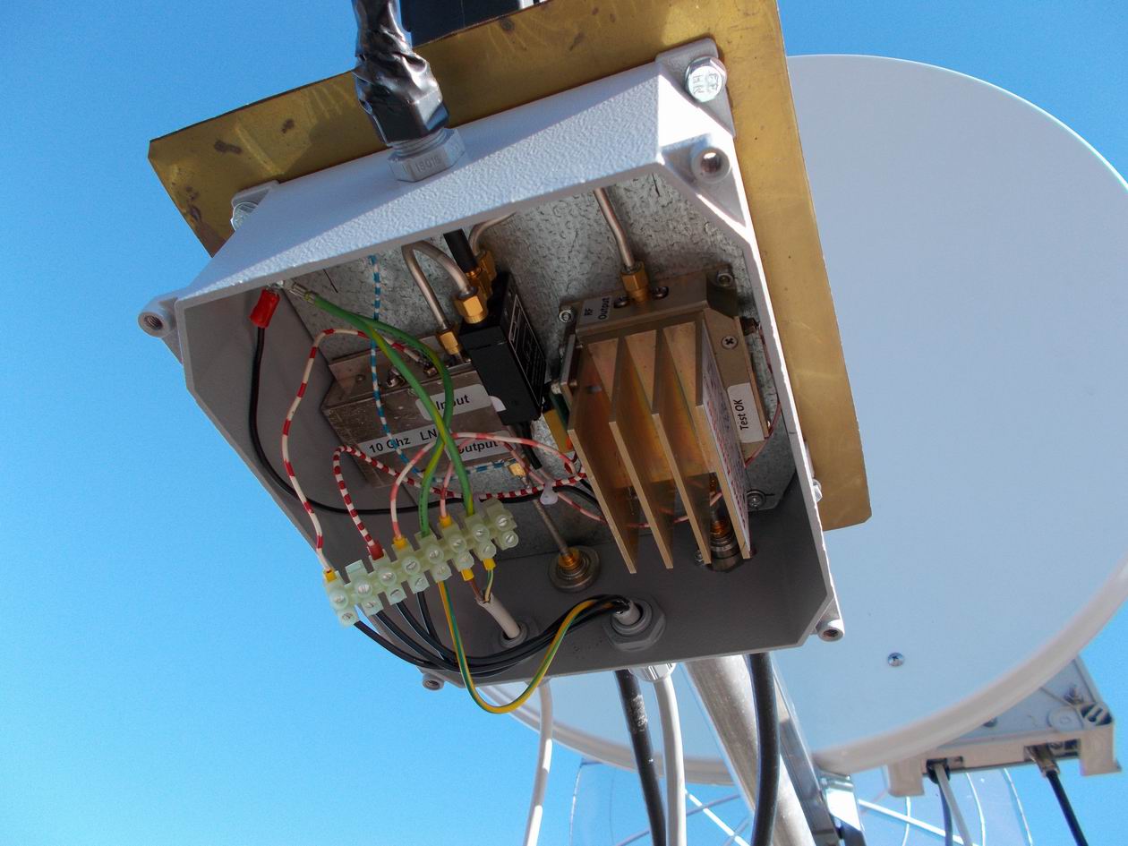
L’illuminatore è collegato al PA+LNA BOX con un cavetto semirigido intestato SMA.
Con questa mia configurazione ho misurato 7 W all’illuminatore.
Disegno del Cablaggio del Transverter
![]()
![]() Transverter for 10 GHz (2016 version)
Transverter for 10 GHz (2016 version)
![]()
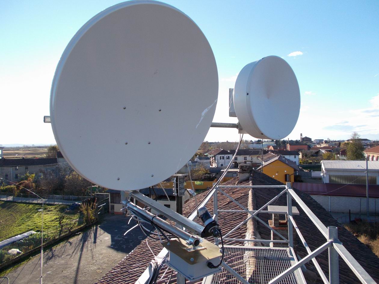
To further
improve the performance of my setup at 10 GHz I thought of making improvements:
transition from the current 4 W to 8 W output and replacement of the 80 cm dish
offset with a 1 meter always offset.
My new transverter for 3 cm is therefore composed as follows:
XVTR MKU 10G2, 4 W PA, 8 W PA, Local Oscillator to 106.500 MHz with input driven
by a synthesizer 10 MHz from Oven, voltage converter (12> 24 Volt) for the
coaxial antenna relays, LNA proceeds modifying a module for receiving TV Sat
SU-02 type and, finally, a sequencer.
To minimize losses I decided to use two aluminum containers for assembly: in one
(as close as possible to the illuminator) there are 8 W PA, the LNA and the
coaxial relay. In the second case we have the MKU 10G2, the 4 W PA, the OL, the
converter 12
>
24V and sequencer.
![]()
It is the most famous, the most coveted
and most powerful transverter new generation of the band of 3 cm. It is located
in kit form or already assembled and tested.
Personally I prefer the version in kit because, in addition to the difference in
cost, there is the satisfaction of having assembled with his own hands. In the
kit there are many SMD components, and some experience for installation is
required. The construction manual explains to first mount all components and
then go to step calibration that is by a normal tester.
Personally I have not followed to the letter the assembly instructions, but I
preferred to install the components in this sequence:
1 – all power supply components and testing
2 – the local oscillator and the calibration of the frequency with the
controlled stability
3 – the RX stage and calibration
4 – the TX stage and calibration
![]()
The local
oscillator is 106.500 MHz. For a good frequency stability I use the synthesizer
designed by F9HX / F5CAU.
The project could always find on this website:
Unfortunately the system with GPS was unstable without understanding why. At
this point I used an oven at 10 MHz in place of GPS and the results were very
satisfactory.
![]()
For
a long time I was planning to increase the output power of my 10GHz transverter
passing between 1 and 4 watts. But he price of the GaAs FET used as a PA is very
high. Some years ago it appeared on the amateur radio markets of power GaAs FET
at a more affordable cost. It was the kind TIM1011-4L and his driver. Beppe
I1GPE and I we bought these drives.
The printed circuit boards purchased them directly from DB6NT, Beppe built the
box for housing the PA. I1GPE built it first and the result was very
satisfactory.
Next time I built the PA for me but the setting made by Beppe.
|
|
|
|
![]()
This PA was built by Piero IZ1EVF.
![]()
It is a low-noise amplifier plate mod.
SU-02. This plate is a double amplifier 4 stages of teflon laminate, originally
used as a low-noise front-end stage for receiving satellite TV to 11 GHz. The
noise figure adhered is about 1 dB.
Detailed information still can be found on
The mod plate. SU-02 is sold by Franco Rota
Interesting applying IZ4BEH Roberto link to
![]()
The sequencer is the same as already used
in other occasions
![]()
![]()
To minimize
losses I decided to use two aluminum containers for assembly: one (called PA +
LNA BOX and near the illuminator) there are the PA from 8 W, the LNA and the
coaxial relay. In the second (called TRXV BOX) we have the MKU 10G2, the PA 4 W,
the OL, the converter 12> 24V and sequencer.
The RF signals at 10 GHz (RX and TX) between the two containers are connecting
by Aircom Plus cable. A multiple cable brings the power to LNA, to PA and the
command to the coaxial antenna relay.
The illuminator is connected to the PA + LNA BOX with a semi-rigid cable by SMA
connectors. With this configuration I measured 7 W to the illuminator.
|
|