Hi, I am Tony I0JX
Enjoy building a low-cost kit for the 4-meter
(70-MHz) band
Rev. 4 - July 23rd 2007
1 FOREWORD
The 70-MHz band (4-meter) is getting available in more and more European countries (see http://www.70mhz.org/) and recently also in Italy (see http://www.space.it/70mhz/). In period mid-May / mid-August of every year long-distance QSOs are possible via sporadic-E propagation. Moreover, during sunspot cycle peak periods, it should also be possible to have transequatorial QSOs between the Mediterranean area and South Africa (ZSs are allowed the 4-meter band).
Availability of radios supporting the 4-meter band is still rather scarce, and many amateurs then use a transverter hooked-up to their HF or VHF rigs (a transverter is a device permitting a transceiver designed to operate on a certain frequency band, to also operate on another band).
A particular cost-effective approach is to get a 6-meter Ten-Tec transverter kit which delivers 8 Watt RF, and modify it for 4-meter operation at assembly time. The modification is here descrìbed with reference to Ten Tec mod. 1209 which is designed to work in conjunction with a 144 MHz transceiver capable of delivering 5 W RF. After the modification, the mod. 1209 transverter traslates the 28 MHz band (instead of 144 MHz) into the 70 MHz band (instead of 50 MHz) and viceversa.
It now seems that the mod. 1209 transverter is no longer available, while the mod. 1208 can certainly still be purchased (see http://radio.tentec.com/kits/Transverter). The only difference between the two is that the mod. 1208 has a 14 MHz input frequency (instead of 144 MHz). Considering that the proposed modification anyway requires moving the input frequency to 28 MHz, there should be little difficulties in modifying mod. 1208 instead of mod. 1209. The mod. 1208 transverter can be ordered directly from Ten Tec at price of 159$ (+ postage and applicable taxes), paying with a credit card.
Please however note that the modification described in Sect. 2 is strictly valid for mod. 1209. Therefore, should one have to modify the mod. 1208 transverter, what written there should be appropriately interpreted. Utilizing mod. 1208 one could even conceive not to modify at all the input circuitry so getting a 14 - 70 MHz transverter.
2 DESCRIPTION OF TEN TEC MOD. 1209 TRANSVERTER MODIFICATION
2.1 General
The extra cost for changing the model 1209 transverter from the 6-meter to the 4-meter band is modest, as only some plain extra components have to be procured. An exception is represented by the conversion crystal, an item that you may probably have to expressly order from a crystal manufacturer and that could cost 10 to 20$. Moreover, it could be a fairly long-lead item.
At this regard there are two main possibilities:
to either procure a 42.000,00 MHz series-resonance crystal, so having the transverter to operate in conjunction with a 28-MHz transceiver (e.g. a 70.000 MHz carrier is translated onto 28.000 MHz and viceversa);
or to more simply use the 94-MHz crystal that originally comes with the transverter. In this case the frequency relationship is such that a 70.000 MHz carrier is translated onto 24.000 MHz and viceversa. This has two main drawbacks:
although most modern transceivers feature a full-coverage receive capability, having a transceiver to also transmit outside the ham bands most often requires a modification, though usually quite simple. Moreover, older transceivers may not be able to transmit in the 24-MHz range;
the conversion scheme inverts bands so that, to operate USB, you have to set your transceiver on LSB and viceversa. Moreover, frequencies go in opposite directions (e.g. a frequency 100 kHz higher than 70.000 MHz, i.e. 70.100 MHz, is translated onto a frequency 100 kHz lower than 24.000 MHz, i.e. 23.900 MHz), and this is quite inconvenient as reading the operating frequency becomes no longer immediate.
The possibility of using the modified transverter in conjunction with a 2-meter transceiver (as the model 1209 originally does) has not been considered, the required crystal frequency being too close to the operational band, this possibly causing spurious emission problems.
The modification described in the subsequent sections refers to the first approach (i.e. using a 42-MHz crystal); however in Sect. 2.7 there are some considerations on the second approach (i.e. using a 94-MHz crystal) should you want to go that way.
The proposed modification is fully reversible, and you can then get the transverter back to work as originally designed by just replacing the changed components and re-tuning the transverter itself.
The Ten Tec transverter is designed for transceivers delivering 5 W output. Modern transceivers permit to reduce output power down to 5 W, but in some cases this may not be possible. If you have problems at this regard, the simplest solution would be to insert an attenuator (capable of handling sufficient power) in between the transceiver and the transverter. This will clearly also cause an attenuation on the receive path, but this should not be a problem because the transverter receive gain is very high and attenuating the signal would anyway be advisable (the receiver noise figure would remain virtually unaffected).
Alternately, you could take a low-level transmit signal from your transceiver (some of the modern transceivers often provide for that signal), but you shall then accordingly modify the transverter input circuitry.
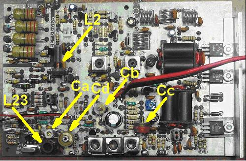
The modification consists in varying the value of some components and adding some extra components. The following picture shows the board, where the modified coils and the added trimmer capacitors are indicated.
We assume that you are going to assemble an unmounted kit. Accordingly, in the following the various phases described in the Instruction Manual are separately addressed.
Remember that wherever in the manual you read:
50 MHz it should now read 70 MHz
94 MHz it should now read 42 MHz
144 MHz it should now read 28 MHz
6 meters it should now read 4 meters
2 meters it should now read 10 meters
2.2 Phase 1.0
Circuit Board Preparation Step
Mount all components as instructed, except for TP2 which is useless and must be omitted to leave room for trimmer Cb (see Sect. 2.5).
94 MHz Crystal Oscillator Board and Diode Mixer
Some of the components must be changed with others of different value:
C53: 15 pF
C54: 47 pF
C55: 6.8 pF
C57: 39 pF
C58: 56 pF
L5: 15 uH
L22: 1uH
L23: this must be replaced with a coil of 6 turns of 0.2 mm wire wound over an 8 mm diameter plastic form with no ferrite core. The coil screen is not used
L24: 4.7 uH
L25: 0.47uH
R60: 68 ohm
Y1: 42 MHz (specify series resonance when ordering)
Mount all components as instructed.
Then add a 20 pF trimmer (Ca) in between Q6 collector and ground.
Test procedure does not change except that, where it asks you to adjust the L23 core, you shall instead adjust Ca. Should you be unable to zero beat the test receiver at precisely 42.000 MHz, then you could try putting a 10 pF capacitor in parallel to trimmer Ca, or rewinding L23 with one turn more or less. Remember that one of the reasons why your oscillator may not be right on frequency is that the crystal manufacturer has not cut it for series resonance.
2.3 Phase 2.0
T-R Voltage Control, RF Input Attenuator
Some of the components must be changed with others of different value:
C6: 10 pF
C8: 4.7 uF
Mount all components as instructed.
Test procedure does not change.
2.4 Phase 3.0 - 50 MHz and 144 MHz Receiving Amplifiers
Part A: Receive T-R Switching at 2-meter Input
Some of the components must be changed with others of different value:
C4: 27 pF
C5: 1000 pF
L1: 10 uH
L4: 10 uH
Part B: 144 MHz post amplifier
Some of the components must be changed with others of different value:
C9: 150 pF
C10: 56 pF
L2: this must be replaced with a coil of 9 turns of 0.3 mm wire wound over a 4.5 mm diameter plastic form with ferrite core. The coil screen is not used. Please pass a small piece of copper wire through each of the two holes intended to support the coil screen and solder them on both printed circuit faces. Then cut the excess wire
L3: 10uH
Part C: 50 MHz Receive Pre-Amplifier
Some of the components must be changed with others of different value:
C43: 33 pF
C45: 22pF
C46: 47 pF
C50: 47 pF
C51: 22 pF
Mount all components as instructed.
Solder the shield cans of L19 and L20 on both sides of the printed board.
With regard to testing, please proceed as follows:
connect a generator set at 70.125 MHz (about 10uV) at the 6 meter IN/OUT
connect an HF receiver set at 28.125 MHz USB or LSB at the 2 meter IN/OUT.
adjust receiver frequency until you hear the generator carrier
tune L2, L19 and L20 for maximum S-meter reading
check that the ferrite cores of the three coils are neither fully in nor fully out. Should this occur:
rewind L2 with one turn less (if core is fully out) or more (if core is fully in)
slightly increase the C45 value (if L19 core is fully in) or decrease it (if L19 core is fully out)
slightly increase the C51 value (if L20 core is fully in) or decrease it (if L20 core is fully out).
No other tests are required for now.
2.5 Phase 4.0
Low-level 50 MHz Transmit Circuitry
Caution: the capacitor which is marked C21 in the electrical diagram is instead marked C22 in the printed board, and viceversa. We here adopt the electrical diagram numbering.
Some of the components must be changed with others of different value/type:
C21: 27 pF
C19: now a 20 pF trimmer capacitor (Cb)
C22: now a 60 pF trimmer capacitor (Cc). Caution: this is a floating trimmer with no end to ground
Mount all components as instructed, but C17, C23, R27 and R30 that shall be simply discarded.
Solder the shield cans of L8, L9 and L10 on both sides of the printed board.
Then add:
a 20 pF trimmer capacitor (Cd) between Q8 collector and ground
Finally, fully remove ferrite core from L8, L9 and L10.
With regard to filter peaking, please proceed as follows:
connect a 20 cm piece of wire at the free end of C25. This acts as a transmit antenna
connect, at the 2 meter IN/OUT, an HF transmitter set at 28.125 MHz FM and adjusted for 5 W RF out
set your local receiver at 70.125 MHz USB or LSB
press the transmitter PTT
adjust receiver frequency until you hear a carrier
adjust Cb, Cc and Cd for maximum S-meter reading (if everything is OK, none of the trimmers shall be at minimum or maximum capacity)
finally set the receiver at exactly 70.125 MHz USB or LSB and, if necessary, then readjust Ca (see Phase 1.0) so as to precisely zero beat the carrier.
2.6 Phase 5.0
Transmit Driver, RF Amplifier, Low Pass Filter
Just one component has to be changed with another of different value:
C33: 68 pF
Mount all components as instructed, but C40, R44 and R46 that shall be simply discarded.
Test procedure does not change.
2.7 Using the 94-MHz Crystal
I have not tried using the original 94-MHz crystal (thus having to operate the transceiver in the 24-MHz range), so I can only give you some hints at that regard. However I see no reason why problems should occur using that crystal, apart from the operating inconveniences mentioned in Sect. 1
Should you decide to use the 94-MHz crystal:
you shall not perform the changes described in Sect. 2.2 under the heading 94 MHz Crystal Oscillator Board and Diode Mixer, as the oscillator remains unchanged with respect to the original design
with respect to what described in Sect. 2.4 under the heading Part B: 144 MHz post amplifier, coil L2 must now resonate in the 24 MHz range, instead of 28 MHz. This may require up to two or three turns more, and/or varying C9 and C10.
I presently see no need for other changes to the modifications.
2.8 Other Modifications
If you wish to have the possibility of varying the output power independently of the 28-MHz drive power, just add a 22-ohm potentiometer (even if wire wound) on the front panel, and connect it in parallel to R6 (47 ohm), using a short length of coaxial cable.
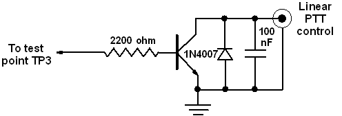
If you need to key the PTT of an external linear amplifier, just mount an RCA socket on the back panel and realize the circuit shown below (which will drive a positive PTT line). Use an NPN power transistor, at least 80 V, 1 A.
3 RESULTS
On a dummy load:
output power, as measured on a Bird wattmeter slug 25B, is more than 10W, i.e. somewhat higher than that of the original 50-MHz design. Anway, when operating FM, it is advisable to reduce drive so as to maintain output power within the design value of 8 W
voice quality is very good.
With regard to reception:
using a signal generator, the transverter sensitivity looks good and its gain very high
using a wideband antenna (a discone), the receiver gets nearly blocked by the very great number of high-power broadcast stations operating in the 88-108 MHz range. This problem, which is also evident with expensive receivers of well known manufacturers, arises from the fact that, in Italy, for at least 20 years they have been giving almost everyone the permit of setting-up an FM broadcast station, with the result that, still today, the number of broadcast stations is incredibly high. However, with a commercial stop-band filter the situation improves dramatically
using a 4-element 4-meter Yagi antenna the background noise caused by the FM broadcast stations is by far lower though still discernible. With a two-cell tuned filter (loss < 0.5 dB) it completely disappears.
Good luck and 73
Tony, I0JX
Return to the I0JX home page