Hi, I am Tony
I0JX
Input Choke & Resonant Choke Power Supplies
for
RF Linear Amplifiers
(by
Tony IØJX & Pesa IKØHIT)
OBJECTIVES
This page discusses the Input Choke Power Supply (ICPS) and the Resonant Choke Power Supply (RCPS), two approaches very well suited to realizing the high-voltage power supply of an RF linear amplifier, them permitting to obtain a very stable output voltage in presence of a varying load (e.g. with SSB or CW operations). In all cases, use of a full-wave bridge-type rectifier is here assumed.
BACKGROUND
The most common type of power supply features a very simple filter, consisting of a plain capacitor (C) directly connected at the diodes bridge output, with a resistor (R) in parallel usually called the bleeder. Let us here call this circuit, shown in Fig. 1, the Conventional Power Supply (CPS).
Fig. 1 The Conventional Power Supply
There are however other approaches offering better regulation performance (i.e. output voltage stability) at the expense of higher complexity and cost; in particular the Input Choke Power Supply (ICPS), in which a choke (L) is inserted between the diodes bridge and the capacitor, as shown in Fig. 2.
Fig. 2 The Input Choke Power Supply
The ICPS is particularly well suited for realising the HV power supply of an RF linear amplifier, mainly because of its inherently stable output voltage. While looking through recent editions of the ARRL Handbook for Radio Amateurs, we noticed that it no longer dwells on the ICPS, probably because of the extra cost and bulk of the filter choke, and of the lower Vout that is obtained for a given Vrms, compared to the CPS. They just mention that ICPSs have become less popular than they once were, because of the high surge-current capability of modern silicon rectifiers allowing to use high-value filter capacitors, thus making it possible to obtain an acceptable regulation performance even with the simpler CPS circuit.
Going further back in time, we could find some discussion of ICPSs, but no mention at all of another interesting type of supply termed the Resonant Choke Power Supply (RCPS). A protracted search on the Internet produced zero hits for the RCPS. The RCPS model is shown in Fig. 3, where one can see that the input choke is now made resonant at the basic ripple frequency (e.g. 100 Hz for 50-Hz mains) by means of an additional capacitor Cr.
Fig. 3 The Resonant Choke Power Supply
The RCPS has voltage regulation properties similar to those of the ICPS, but it allows using a much smaller choke and/or dissipating much less power in the bleeder.
That
said, Pesa and I decided to write this page, in the hope of preserving
what seems to be a vanishing bit of
knowledge.
CONVENTIONAL APPROACHES
To better appreciate the advantages of ICPS and RCPS, let us first consider other more common types of rectifying circuits.
In the CPS case (see Fig. 1), for zero current (i.e. both R and external load = ¥), Vout=1.41*Vrms (1.41 is the sinusoidal wave peak-to-RMS ratio). This occurs because C gets charged, through the diodes, up to the peak of the transformer output voltage.
When a load is applied to the circuit, Vout tends to drop, this effect occurring even under ideal conditions, i.e., zero-resistance transformer windings, zero-drop diodes, mains voltage independent of load, etc. The graph shown in Fig. 4 shows the simulated relationship between Vout and the DC output current Iout for a circuit with ideal components.
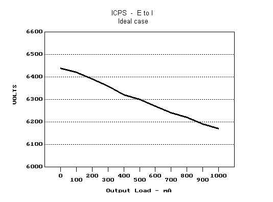
Fig. 4 DC Output Voltage Vs. Current For A Conventional Power Supply
Assumptions
made for obtaining above results are:
transformer
secondary
RMS voltage: 4550 V
reservoir
capacitor (C): 15 mF
bleeder
(R): ¥
With ideal components, increasing capacitance always turns into a reduction of voltage drop; conversely with real components there would be no advantage in increasing C beyond a certain value (see graphs in the ARRL Handbook); furthermore regulation will always be worse than for the ideal case, mainly due to voltage drops in transformer windings.
The
purpose of the bleeder (R) is two fold:
as
a safety precaution, to discharge C when the power supply is
turned off;
to
reduce, to a certain extent, Vout
under no-load conditions
(e.g. during reception, when the amplifier tube is interdicted). This may
also be helpful in prolonging the capacitors life if Vout
is
close to its rating, and to reduce the plate voltage if
it is close to the tubes limit.
Choosing a value for R is however rather arbitrary; no value is a clear optimum.
With the CPS, the diodes are subjected to very high surge current (occurring when C gets charged at each AC cycle). Many years ago, high surge-current rectifiers and high-capacity electrolytics were not yet available, and it was then necessary to apportion the filtering function among several elements, rather than demanding it to just a single capacitor. At that time the rectifying circuit shown in Fig. 5, having two extra filtering elements, i.e., a choke (L) and an extra capacitor (Cf), was fairly common. In practice this circuit may be regarded just as a CPS with an extra L-C low-pass filter
Fig. 5 A Distributed Filtering Approach
From
the conceptual point of view,
there appears to be little difference between the scheme of Fig. 1 and that of
Fig. 5. In
particular, similar Vout/Vrms
and Vout/Iout relationships
should be expected, though
the actual voltage drop will depend on the C, Cf and
L values. It should be noted
that now also the L winding resistance
contributes to the total voltage
drop budget; in
conclusion, this solution does not seem worth the greater component count,
taking also into account the fact that RF
linear amplifiers do not typically require a particularly well filtered DC
supply.
THE INPUT CHOKE POWER SUPPLY
Let
us now consider the ICPS approach depicted in Fig. 2. This type of circuit displays a totally different
relationship
between Vout
and output current.
As a matter of fact, in theory:
if the value of L exceeds the so-called critical value Lc (see later), under ideal conditions Vout remains stable at about 0.9*Vrms, independently of the output current Iout (the 0.9 factor is the average-to-RMS ratio for an ideal full-wave rectified sinusoid)
if
the value of L is instead lower than Lc,
Vout rises beyond
0.9*Vrms: the lower
L, the
higher Vout, and the worse the power supply
regulation. At the limit, for L
= 0, Vout=1.41*Vrms
(the circuit of Fig.
2 would in effect coincide with
that of Fig. 1).
It should however be noted that the critical value Lc is not a fixed parameter, it varying with Iout and being approximately given (in Henry) by:
Lc=Vout/Iout for 60 Hz operation (as given in the ARRL Handbook)
Lc=1.2*Vout/Iout for 50 Hz operation
where Vout is expressed in V and Iout in mA.
Then, when selecting a value for L, one shall do it with regard to the maximum value that Lc can have, i.e., that occurring when Iout is minimum. The justification for Lc and its value is given in the Technical Annex at the bottom of page.
All the above is valid for ideal components and under the assumption that C shows a very low reactance at twice the mains frequency (say less than 100 ohm); in practice a capacitor of 15 to 20 mF is usually selected for power supplies providing a Vout of 3000 to 4000 V.
Having
selected
a certain value for L at circuit design time, we can describe the situation that
develops as follows: Vout
remains constant at 0.9*Vrms
until total current (load + bleeder) is high enough that Lc
remains lower than L;
for lower currents,
when Lc
becomes higher than L,
Vout
tends to
increase, reaching, at the limit, 1.41*Vrms
for a zero total-current condition.
It is therefore evident that, to obtain an ICPS providing constant output voltage at all times, one must ensure that some minimum current is always absorbed, even when the external load takes none. This task is demanded to the bleeder (R), the selection of which is much less arbitrary than for the CPS: the higher is the minimum current drawn, the lower is the maximum value that Lc will have, and hence the lower will the design value for L be.
When undertaking a practical ICPS design, difficulties immediately arise when trading off the amount of residual current (Imin) with the value of L:
for reasonable values of L, the corresponding Imin is typically quite high, with excessive power being dissipated in the bleeder;
conversely,
for
a reasonable dissipation in the bleeder,
the value of L
is usually rather large, this fact resulting in a bulky and expensive choke, potentially also
causing too high a voltage drop due to the extra resistance of the
greater number of turns required.
To mitigate the above problems, there are at least three possible escapes:
if one accepts that, while transmitting, Vout remains equal to 0.9*Vrms across the whole tube working region (from zero to maximum RF drive), but, during reception when tube is interdicted, Vout can instead rise somewhat, then it would be possible to reduce the bleeder power dissipation, in virtue of the fact that the tube idling plate current would implicitly take a good share of the needed Imin. This technique is commonly adopted, but care has to be taken that, during reception when the Lc becomes higher than L, Vout does not exceed the applicable capacitor and tube ratings;
as discussed later, using an RCPS instead of an ICPS would significantly help relaxing the trade-off between Imin and L;
to adopt a more effective choke design (the so-called swinging choke), that offers a higher inductance and lower resistance for a given physical size.
With regard to the latter item, it should be noted that
filter chokes are traditionally built by piling
E-shaped laminations on one end, and I-shaped laminations on the
other, as shown in Fig. 6, such as to intentionally create an air gap causing
the magnetic path resistance to increase significantly.
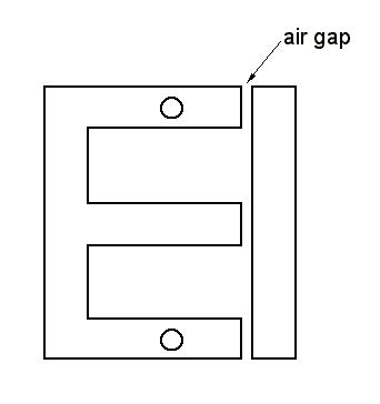
Fig. 6 Traditional Choke Construction Technique
Such
high resistance retards magnetic material saturation, thus making choke
inductance nearly independent of DC current flowing through the choke itself.
Swinging chokes are instead built in the same way as transformers, i.e. alternating E-shaped and I-shaped iron laminations, so as to minimize the magnetic path. This has two main effects:
for a given choke size, a higher inductance is obtained;
the absence of the air gap causes the DC current to easily saturate the material, thus resulting in a strong decrease of choke inductance (hence the name swinging choke). This behavior is however not a problem for an ICPS, as the Lc value that choke inductance must exceed to keep Vout at 0.9*Vrms also decreases with DC current.
Using swinging chokes then appears to be an ideal solution for ICPSs.
It
should be noted that,
if one would hypothetically succeed in designing a choke the inductance of which
decreases so much
with DC current that, at
high currents, choke inductance falls below Lc
and Vout
consequently increases, the unavoidable voltage drop caused by
the choke and transformer windings ohmic losses could be compensated for
somewhat.
Appropriate choke design may then result in a kind of self-stabilized power supply. However,
ICPS regulation is
usually good enough, even without optimising the inductance-to-current response.
One of the advantages of ICPSs is that the current in the transformer windings is sinusoidal, whilst, with CPSs, current takes the form of short high-value peaks. As dissipated power grows with the square of current, for a given average current the power lost in the transformer copper will be lower for ICPSs, this simplifying the transformer design.
As an example, some broad guidance is here given for designing a ICPS intended to provide 4,000 VDC at 1 A, with a tube plate idling current of 150 mA. Taking into account the unavoidable ohmic losses, a Vrms of about 4,500 V would seem appropriate. An adequate value for C would be 20 mF or even less.
Selecting an 80-Kohm bleeder, drawing 50 mA, would imply a fairly affordable dissipation of 200 W. The total minimum current (Imin ) on transmission would so become 200 mA, with a corresponding Lc of 20 H at 60 Hz, or 24 H at 50 Hz. At maximum plate current, the total load would become 1.05 A, this causing a reduction of Lc down to 3.8 H at 60 Hz, or 4.6 H at 50 Hz..
The choke shall be designed such that L>Lc for all currents within the operating range. This requirement is most constraining at the lowest current (200 mA), it resulting into an L of at least 20 H for 60 Hz, or 24 H for 50 Hz (these are the minimum values, to be measured at 200 mA). Conversely, at the maximum current (1.05 A), though at that current the choke inductance would probably get down to about 10 - 12 H (a typical swinging factor of 2 for an about 400% current increase should be expected on the basis of measurement results reported below), such values still largely exceed the low Lc that corresponds to that current.
On reception (tube interdict), one should expect Vout to exceed 0.9*Vrms, as Imin drops down to only 50 mA, this causing Lc to exceed L. Appropriate precautions should be taken at this regard; if one wants to reduce Vout during reception, there is no other way than using a higher-inductance choke or a lower-resistance bleeder, but this may actually result to be unaffordable.
To conclude, Alan G3XAQ reported a potential problem with ICPSs, related to their dynamic response during SSB speech or CW keying. When the current demand changes, perhaps by a factor of 10, with a swinging choke Vout could oscillate at the resonant frequency of the L-C circuit. A very strong oscillation at around 10 Hz, lasting for several cycles was observed in some particular cases, but this effect can be avoided by proper L and C selection.
THE RESONANT CHOKE POWER SUPPLY
Despite the benefits that swinging chokes can offer, a typical ICPS remains rather bulky and expensive. To improve on this situation, the RCPS approach (see Fig. 3) has been proposed at least since the late fifties, and adopted in high-end linear amplifiers, such as the Collins 30S-1 and most Henry Radio amplifiers.
The underlying idea is that a choke, when made to resonate in parallel with a capacitor (Cr), would constitute a filter showing an much greater impedance, this fact opening the road to using smaller value chokes. In Europe, the resonant frequency of the filter must be 100 Hz, i.e., the fundamental ripple frequency of a full-wave rectifier. If equipment designed for the US market is to be used in Europe, the value of Cr must be increased in order to move resonance from 120 Hz down to 100 Hz; please note that there is a very significant change in performance if a 60 Hz design is directly used at 50 Hz.
However, as better explained in the Technical Annex at bottom of page, the resonant choke can only block the fundamental frequency at 100 or 120 Hz, but it will typically show a lower impedance than a plain choke for the harmonics, the level of which is not negligible at all. Nevertheless, the RCPS offers a great improvement with respect to the ICPS, in that the required choke inductance becomes roughly one order of magnitude lower than for the ICPS case. Also, a lower ripple should be expected for a given C, it only containing higher-frequency components.
Use of a swinging choke is possible, and recommended, also for the RCPS; at this regard it should be noted that the inductance reduction caused by the circulating DC current detunes the filter. However, this may be beneficial, as the consequent Vout increase contributes to partially recover the voltage drop caused by the inevitable ohmic losses of the various supply components.
Once you have decided the desired output voltage VDC and the minimum DC current Imin (i.e. the bleeder current, plus the tube idling current if you will) on the basis of dissipated power considerations, you can use the following approximate formulas to design your RCPS, which are valid at 50 Hz and for a 4% overvoltage at minimum current:
Vrms=1.11*VDC
L>0.11*VDC/Imin (in Henry, measured at minimum current)
Cr=1/(0.394784*L) (in mF, selected for resonance)
where Imin is expressed in mA and VDC is expressed in V.
At 60Hz, L will have a minimum inductance about 17% lower than that calculated by the above formulas. With regard to C, a value of 15mF or higher is usually adequate.
In practice some cut and try may be required due the non-ideality of components.
Let us now revisit the ICPS example presented above for guidance purposes, trasforming it into an RCPS with the same parameters (i.e., DC output voltage 4,000 V, maximum tube plate current 1 A, plate idling current 150 mA and bleeder current 50 mA).
Profiting of the smaller choke required for an RCPS, it seems now viable to design the power supply so as not to exceed 4,000 V by more than 4% even during reception, when the tube draws no idling current. Accordingly, we will here then assume Imin=50 mA.
From the above formula, the minimum value for L is 8.8 H (at 50 Hz). If we use a 9 H choke (measured at 50 mA), the resonance capacitor Cr will be 280,000 pF. Note that Cr shall typically have a voltage rating of 8,000 to 10,000 V (suitable capacitors are shown below) and their capacitance shall be precise.
In conclusion, using a choke having an inductance nearly one third of that of the ICPS, we now have a less bulky and expensive power supply providing a nearly ideal voltage regulation at all times.
Now some real measurements made on my Henry Radio 4K-ultra
linear amplifier which utilizes a RCPS. This equipment is basically built for
60-Hz operation, but, for the European market, the value of Cr
is factory adjusted for 100-Hz resonance. The main supply parameters are listed below:
R: 80 kW, drawing a current of about 50 mA at 4000 V;
Cr
(resonance capacitor): 0.27 μF. This capacitor originally was 0.3 μF
(nominal), but I have experimentally adjusted it for minimum output voltage at 50 mA current;
C
(reservoir capacitor): 15 μF,
with 5 kV rating;
L:
reckoned (by formulas and circuit simulation) to be around 9.25 H at 50 mA.
A
fairly similar Collins power supply has
a choke marked 8 H, lending credence to the derived value of 9.25 H;
Vrms:
4550 V
VDC:
4350
V @ 50 mA (tube interdict, bleeder only):
4050
V @ 270 mA (bleeder
+ tube idling current of 220 mA);
3950
V @ 1050 mA (bleeder + tube full current of 1 A).
Regulation
is about 2.5% across the whole tube working region; quite an achievement if one
considers that there is no compensation at all for the transformer
and choke resistive losses!
The
circuit has been simulated by dimensioning the unknown parameters so as to obtain simulation results as
close as possible to the measured ones. The
voltage-to-current relationship, presented in Fig. 7, shows an evident knee, as
expected.
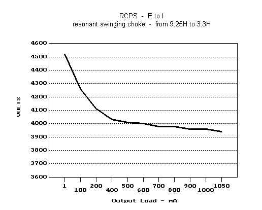
Fig. 7 Simulated Output Voltage Vs. DC Current For The Henry 4K-ultra RCPS
The above data fairly well match those of the RCPS example presented earlier, which were determined by means of formulas.
It
appears clear that the bleeder current of 50 mA was chosen
by Henry as a compromise
between power dissipation and voltage increase when the tube is interdicted (i.e.
during reception).
It
is not easy to precisely predict how much choke inductance drops at maximum current.
Simulation results indicate a value of 3.3 H @1.05 A. This seems reasonable; furthermore the ratio 9.25 /
3.3 = 2.8 appears to be plausible when
compared to figures mentioned in the ARRL Handbook.
Simulation
results
also show that, should choke inductance @ 1.05 A instead drop below 2.8 H, the power
supply would effectively display an ideally steady regulation. This suggests
the idea of controlling the choke inductance variation with the aim of keeping the output voltage
perfectly constant throughout the current range. Discarding cut and try at the outset, one
could think of a feedback circuit modifying choke inductance by, for example,
varying the DC current flowing through an additional choke winding. Any ideas?
Fig. 8 plots the voltage transient across the choke at 1.05 A for L=3.3 H.
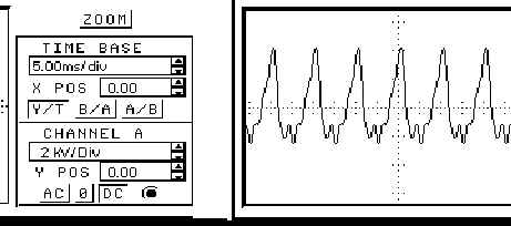
Fig. 8 Voltage Transient Plot
The steady state pk-to-pk AC voltage across the choke, with the inductance progressively reducing, is given it Tab. 1.
|
Transient
on switch-on, |
8.0 |
9.25 |
|
Steady
state @ 50
mA, bleeder only |
5.4 |
9.25
H |
|
Steady
state @ 270 mA, tube
standby |
6.0 |
9.00
H |
|
Steady
state @ 1050 mA, full work load |
6.4 |
3.20
H |
Table 1. Peak-to-Peak Voltage Across The Choke
The
above results show
that capacitors rated at 8 kV or higher should be used. Clearly, also the choke
shall have the same lead-to-lead voltage rating; simply add the DC voltage
to the peak AC voltage to
determine the choke-to-ground insulation.
The
low-capacity high-voltage capacitors required to finely trim the resonant
capacitance Cr
are not common at all; I was lucky to find some surplus oil-filled
capacitors with a glass shell that fit the bill. Those shown in Fig. 9 are: 0.01 μF (green), 0.02 μF (white), 0.03 μF (yellow),
0.05 μF (red), with voltage ratings varying from 7.5 to 10 kV.
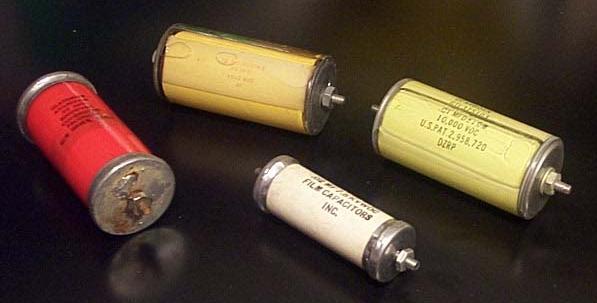
Fig. 9 Suitable Oil-Filled Resonance Capacitors
Both
simulation and trials indicate that the Cr
value is quite critical; ideally one
should try to match the optimum value to within ±0.005 μF or so.
To conclude, look at Fig. 10, where the so-called "Hay bridge" is shown. This is a circuit specifically intended to measure choke inductance in the presence of a DC current. It was just taken from a very old book.
Fig. 10 The Hay Bridge
Pesa
and I remain available for any further clarification or suggestion.
TECHNICAL ANNEX
Let us begin explaining the reason why, for an ICPS (see Fig. 2):
Vout=0.9*Vrms independently of load (when L>Lc)
Lc=Vout/Iout at 60 Hz (or 1.2*Vout/Iout at 50 Hz).
Let us start from an hypothetical unfiltered rectifying circuit, shown in Fig. 11.
Fig. 11 An Unfiltered Rectifier
Said circuit contains no reactive elements (i.e. capacitors or inductors). The corresponding Vout time plot at 60-Hz is presented in Fig. 12, for Vrms=1,111 V.
Fig. 12 Output Voltage (Vout) Vs. Time For An Unfiltered Rectifier
As expected, Vout peaks at 1,572 V, i.e. 1.414*Vrms. The red line shows the waveform average, i.e. the level of the DC component (VDC), which is equal to 1,000 V, i.e. 2 / P times the Vout peak, or more simply 0.9*Vrms.
Fig 13 shows the Vout spectrum, still for Vrms=1,111 V.
Fig. 13 Output Spectrum For An Unfiltered Rectifier
The graph shows that, within Vout, it is possible to distinguish:
a DC component (VDC) equal, as already mentioned, to 0.9*Vrms, i.e. 1,000 V
an AC component (VAC) resulting from the sum of all other spectral lines, and containing:
no energy at the mains frequency (60 Hz), this being due to the assumed use of a full-wave rectifier which effectively acts as a frequency doubler
a strong spectral line at twice the mains frequency (120 Hz), having a peak value of 0.666*VDC
harmonics, the peak level of which decreases at increasing frequencies (0.133*VDC, 0.056*VDC, 0.031*VDC ...)
The waveform of the current (Iout)
flowing through R is identical to that of Vout
(the load being purely resistive), and then has the same spectral composition.
Let us now pass to consider practical circuits (e.g. those of Fig. 1 and 2), in
which one or more reactive elements are instead present. Following the general
rule that,
in the steady state, reactive elements cannot alter the DC component, one may hurriedly conclude that VDC
must in all cases remain the same as without the reactive element(s), i.e. 0.9*Vrms,
independently of the value of those elements. Along the same reasoning, also the
DC component of Iout
should be unaffected by the presence of reactive elements.
In practice this is not always
true; for instance, in the case of a CPS (see Fig 1) it is well known that the
presence of C causes VDC
to grow up from 0.9*Vrms
to a theoretical maximum of 1.41*Vrms;
conversely, in the case of an ICPS (see Fig. 2), voltage stays at 0.9*Vrms
if L>Lc,
but it tends
to grow up if L<Lc.
So, the reactive elements do not seem to always yield the same effect.
Such a situation can be explained by the presence of a non-linear element, i.e. the
diodes bridge which can only draw current in one sense, but not in the other
one. In presence of non-linear elements, the value of VDC
will depend on whether or not the reactive elements alter the duration of the diodes ON-OFF
periods.
For instance, in a CPS (see Fig. 1) the diodes ON-OFF periods is significantly
altered by the presence of C (the voltage of
the charged capacitor causes the diodes to conduct for only a small fraction of the sinusoidal cycle);
conversely in a ICPS (see Fig. 2), if L<Lc
the diodes switching sequence is not altered by the presence of L
and C, and VDC
then stays at 0.9*Vrms
(in reality it would be more correct to say that Lc
is the minimum value that L must have value not
to alter the diodes switching sequence).
That said, a simple way to more precisely assess the behaviour of an ICPS (see
Fig. 2) is:
to initially assume that the diode switching sequence is not altered by the presence of L and C;
and to then determine under which conditions said assumption becomes no longer true.
Proceeding that way, the voltage at the diodes bridge output (Vb) clearly has the same waveform as in the unfiltered case (see Fig. 12), this meaning that its DC component is equal to 0.9*Vrms. Clearly, also VDC will have the same value. Then, the DC component of the diodes bridge output current (flowing through L and R) will clearly be equal to VDC/R.
Let us now consider the AC
component of the diodes bridge output current (flowing through L
and C).
Such current mainly depends on the value of L, if we here assume that C is high
enough to nearly represent a short circuit at twice the mains frequency.
Furthermore, for a given value of L, the current
spectral composition will have a different shape from that of voltage, L
showing a higher reactance for the higher-frequency harmonics. Actually, the
current waveform will be smoother than that shown in Fig. 12 with regard to
voltage.
The total diodes bridge output current will be the sum of its DC and AC
components: it is immediate to conclude that TO AVOID ALTERING THE
DIODE SWITCHING SEQUENCE (and hence to guarantee that VDC
stays at 0.9*Vrms)
the total AC + DC current shall never TEND to become negative, such a polarity change being
expected if the negative peak of the AC current component exceeds that of
the DC current component (in reality, current cannot become negative, because the
diodes would not allow it).
At this point we shall just compare
the two components, to determine the current sign inversion point.
While the DC current component (IDC)
is simply equal to VDC/R (or
0.9*Vrms/R),
the negative peak of the AC current component (IAC)
can be estimated on the basis of the following facts:
the peak amplitude of the main 120 Hz spectral line was shown to be 0.666*VDC
the corresponding peak current is obviously 0.666*VDC/Zl, where Zl is the reactance of L, equal to 2*P*120*L, i.e. 754*L ohm
but, to calculate the real value of the negative peak of IAC, one must also consider the contribution of the harmonics, which are attenuated by L more than the 120-Hz line is. For reasons that will become evident later, let us assume that harmonics cause an increase of the peak current formula multiplier from 0.666 to 0.754. Such assumption would imply that the harmonics contribution to the total peak current is about 13%, a reasonable value if one considers that they cause an increase of the negative peak voltage of about 50%, i.e. from 0.666*VDC to VDC, but the corresponding current increase should be much lower due to the higher reactance of L at higher frequencies.
The current inversion point would then occur when:
IDC = IAC = 0.754*VDC/Zl = (0.754*VDC)/(754*L) = VDC/(1000*L)
Expliciting L:
L=VDC/(1000*IDC)
If we keep L in Henry and VDC
in Volt, but we express IDC
in mA instead of A, we obtain:
L =VDC/IDC
So, by the assumption taken above we were able to obtain the same formula shown
in the ARRL Handbook, which is however approximate, as the contribution of harmonics to IAC
was only estimated, and anyway varies with
L.
In case of 50-Hz operation, the amplitude of the spectral lines shown in Fig. 13 will not change, though those lines now obviously occur at multiples of 100 Hz. So, the above reasoning can be readily extended to the 50-Hz case, by only adjusting the value of L so as to still show a reactance of 754*L ohm at 50 Hz. This means that at 50 Hz, for the same bleeder value and regulation performance, L shall be 20% greater than at 60 Hz.
Let us now pass to consider the RCPS (see Fig. 3), still under the assumption that C is high enough to represent nearly a short circuit for all AC components. The filter formed by L and Cr is made resonant at twice the mains frequency, this virtually preventing any current component at that frequency to circulate. Nevertheless, AC current, now only formed by the harmonics, will still be drawn through the filter because of its finite reactance at the harmonics frequency.
One important RCPS optimization parameter is then represented by the Q of the resonating circuit. As a matter of fact the desired resonant frequency can be obtained for different combinations of L and Cr. Decreasing Q (higher L and lower Cr), less AC current would be drawn through the filter because of its higher impedance at the harmonics frequency, and less minimum DC current would then be required not to alter the diodes switching sequence (and hence to keep VDC at 0.9*Vrms), just as discussed for the ICPS case.
In conclusion, the basic RCPS trade-offs look similar to that of the ICPS. By increasing L it is possible to reduce the bleeder current and viceversa. The main advantage of the RCPS is that, for a given bleeder current, a smaller (properly resonated) inductor can be used.
To have an idea of the impact of the resonant choke, we could imagine to modify the waveform shown in Fig. 12, by removing the 120-Hz spectral line from the tension (Vb) feeding the filter, as that line can produce no current due to the extremely high filter impedance at the resonant frequency. Doing so, the Vb waveform would become that shown in Fig. 14, which was derived from that Fig. 12 by simply suppressing the 120-Hz spectral line. Obviously, no change occurs with regard to the DC component (VDC is still equal to 1,000 V), and to the harmonics amplitude.
Fig. 14 Diodes Bridge Output Voltage Without The 120-Hz Component
Without the strong 120-Hz contribution, the negative peak amplitude now gets much lower, i.e. from VDC (as in Fig. 12) to 0.307*VDC, but the AC current through the filter will not diminish as much, because the resonant circuit shows a much lower reactance than the plain ICPS inductor at the harmonics frequency.
To assess the RCPS behaviour recourse must be done to mathematics, so I preferred to perform some simulations, assuming the use of ideal components (effects such as ohmic windings resistance, or choke capacitance, or inductance reduction with DC current were not taken into account in the simulations).
The simulated case was a 50-Hz RCPS delivering 3,000 VDC with C = 20 mF, L ranging from 1 H to 10 H, Cr selected such as to resonate the choke at 100 Hz in all cases, and the bleeder R adjusted so as to obtain just a 4% voltage increase when there is no external load. The graph shown in Fig. 15 was obtained.

Fig. 15 RCPS - Required Bleeder Current At 50 Hz For 4% Overvoltage Under No Load
Comparing the RCPS with the ICPS, it comes out that the L values shown in Fig. 15 are consistently about 11 times lower the those required for an ICPS at the same bleeder current, on the basis of the L>Lc equation.
Further simulations were carried out to assess the dependance of L with VDC and the minimum DC current. The obtained results permitted to determine the RCPS design formulas reported in the main body of this page.
Return to the I0JX home page