Hi, I am Tony I0JX
Feed your radios using inexpensive
PC power supplies
CAUTION: when opening the case of a PC power supply, remember that some of the internal components work at high voltages (up to 400 V) that can be lethal! You shall then pay maximum care not to touch any component. Such voltages may remain even after removing the AC power: remember to always discharge the high voltage capacitors before doing anything else!
FOREWORD
Hundred-watt transceivers typically consume up to 22 A @13.8 VDC. To power such radios you may either use a (today obsolete) conventional regulated power supply, or a smaller, lighter and more efficient switching supply, that would cost you 110$ as a very bare minimum. Although this is a price that most people can afford, if you still like playing with electronics and anyway want to save as much as 90% of that price, you may consider building your switching power supply using surplus PC supplies that you can easily find at 5$ each, or even get free if you have access to an appropriate source. In my case, I was able to salvage a great number of PC supplies, just before the obsolete PCs stock of my company was going to be cleared. Nearly all supplies were found to be fully functional; however this may not be the case if the supplies instead come from a PC service centre, as there is a good chance that some of them are defective units taken out of faulty PCs.
We here assume to utilize PC supplies as they are, with almost no modifications. If you are instead prepared to carry out significant modification work, you may also consider the solution proposed in this link.which however deals with a specific type of supply that may not be easy to find.
BASICS
First of all let us note that there are two general categories of PC power supplies, namely those of the AT-style cabinets (used for old PCs up to Pentium MMX, and usually having a maximum power of up to 375 W), and those of the ATX-style cabinets (used starting from Pentium II, having a different case and a maximum power of up to 600W).
The AT supplies generate four voltages, namely +12V, -12V, +5V and -5V. Maximum current varies as a function of the supply power, as shown below.
|
Supply Nominal Power |
Nominal DC Current |
|||
|
+5V red wires |
+12 V yellow wires |
-5 V white wire |
-12 V blue wire |
|
|
200 W |
20 A |
8 A |
0.5 A |
0.5 A |
|
230 W |
23 A |
9 A |
0.5 A |
0.5 A |
|
250 W |
25 A |
10 A |
0.5 A |
0.5 A |
|
275 W |
27.5 A |
11 A |
0.5 A |
0.5 A |
|
300 W |
30 A |
12 A |
0.5 A |
0.5 A |
|
375 W |
37.5 A |
15 A |
0.5 A |
0.5 A |
Notes:
The higher-power ATX supplies will obviously withstand more current. Those supplies also deliver other voltages (e.g. 3.3 V, a high-precision 5 V, etc.). The AT supplies do not fit the current ATX-style cabinets, so they are easier to find at low cost. Therefore we will here focus on the AT supplies, although what written here should be of quite general validity.
There are quite a number of different PC supplies manufacturers, each adopting a different circuit, although the most critical components, e.g. the main transformer, appear similar. Looking at the various diagrams, one can easily determine that the four voltages are always generated by separate secondary windings of the same transformer, this meaning that the voltages are not independent of each other.
An important question is how many PC supplies shall one use to generate 13.8 V at the required current of 22A. The 12 V output cannot be used as such, because voltage is too low (1.8 V less would make a lot of difference). I would hesitate to adjust the supply for bringing that voltage up to 13.8 V; on the other hand the available current is also too low (no more than 10 A for commonly found supplies generally having a power not higher than 250 W), so no big deal anyway.
Then, the only possibility which makes sense is to utilize three supplies, putting the +5 V outputs in series, and then decreasing their voltages until the total voltage gets to the desired value.
Unfortunately, PC supplies do not have a direct voltage adjustment control, so one of the problems to be solved is how to lower voltages (this is discussed later). From this viewpoint, please consider that:
Not using the 12 V high-current output at all permits the supply to operate at much less total power than the permissible maximum (roughly one half of that). So, most of the supply components will operate at reduced load, this fact greatly increasing the overall supply MTBF (Mean Time Between Failures). As a last remark, PC supplies incorporate short-circuit protection circuitry, that shuts power down when current exceeds a given threshold.
INITIAL FUNCTIONAL TEST
After procuring three PC supplies, all having a power not lower than 200 W, the first thing to do is to verify that they work properly. To do this, you shall simply power each supply using an appropriate AC cord and measure voltages.
Unless your supply has an integrated power switch, you will see a four-wire (+ ground) black cable that connects the supply to the power switch. Most likely the switch has been cut out, so the black wire will have an open end. Obviously, to make the functional test, you shall simulate having put the power switch to ON. Then, at the open end of the black cable, short the blue wire to the white wire, and also short the brown wire to the black wire (it looks like that all manufacturers adopt the same color coding, however it would be safer to check the internal wiring before powering the supply).
Once the supply gets powered, you should immediately hear the fan noise. Sometimes fans are defective; either they simply do not work or they are noisy. In either cases, you should replace the fan or the whole supply.
Then measure the four voltages between the black wires and the coloured wires (see table above). As mentioned earlier, voltages should be at the nominal value plus/minus half a volt. In some rare cases, the supply may not work if there is not a minimum load. In that case you may place e.g. a 24 ohm 10 W resistor on the 12 V output (so drawing 0.5 A). The real need for it also depends on the way you expect to utilize the supply.
Once you have measured that all four voltages are correct, you should also verify the regulation of the 5 V line of your supply, i.e. the voltage drop in presence of a load. Such test is advisable because the various PC power supplies are not identical at this regard, and some of then behave better than others. As a matter of fact, the internal voltage stabilization circuit can operate on either the +5 V line, or on the +12 V line or on both, and this makes quite a difference from the regulation viewpoint. In conclusion, before proceeding you should better check that the 5 V line of your particular supply has a good regulation.
To do that, connect a 0.22 ohm resistor on the 5 V output (that will draw about 22 A), and quickly verify that the voltage drop does not exceed about 0.2 V. A 15 W resistor could be adequate, provided that the test does not last more than a few seconds.
If the voltage drop is too high, you may try the hints given in the section dedicated to regulation, before using another type of supply.
CLEANING THE SUPPLY
Apart from dusting, it is also necessary to make some changes in the wiring layout :
At that point it is safe to check that the power supply still works, by applying AC power to it and measuring +5 V between any of the red wires and any of the black wires.
INSULATING THE BOARD FROM THE ENCLOSURE
In all supplies, the metal enclosure is connected to the supply ground (i.e. the black wires coming out of the printed board). Therefore, with the supplies connected in series, the three enclosures would not be at the same potential. This would be a nuisance, as one should take care that the enclosures do not touch each other.
The most straightforward approach to solve this problem is that of insulating the enclosure from the supply ground, and then connecting the three enclosures together. This solution is shown below.
Please note that insulating the enclosure is not needed for the bottom supply of the series. In this way, the three enclosures will all be at ground potential.
The enclosure gets connected to the supply ground through the binding posts on which the printed board is fixed (by means of four screws). To explain this better, let us give a look to the copper side of the board (not all boards may however be identical to the one shown below, so you may have to adapt the procedure to your particular case).
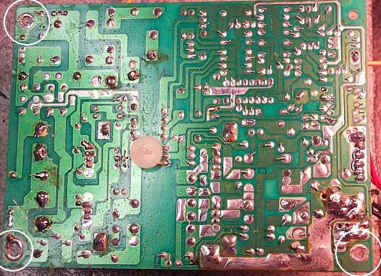
Except for the top-right hole, the other three holes (identified by white circles) bear a copper pad that is connected to some components of the board. When the board is in place, those three pads are in direct contact with the enclosure support posts. Therefore, the issue is to insulate those pads, so that they will not touch the support posts.
To be more specific:
the pad to which the black wires are connected (i.e. bottom-right pad) is the real supply ground: that is the pad which must be insulated from the enclosure. In some supplies there are two pads electrically connected to the black wires; in those cases you must insulate both of them;
the pads to which only the AC line bypass capacitors are connected (i.e. the left-top and the left-bottom pads) should instead not be insulated, and then left touching the enclosure support posts. Those high-voltage capacitors are very easy to identify.
To insulate pad(s) from the support post(s), just put (a) plastic washer(s) in between the pad(s) and the post(s), and verify that the metal screw(s), once tightened, will not short the pad(s) to the post(s). Once all four screws have been properly tightened, check that there is no electrical continuity between any black wire and the enclosure.
ADJUSTING VOLTAGES
Three supplies in series would produce too high a voltage for our purposes. A quick way to solve this problem would be to put one, or perhaps two, silicon diodes in series with the 13.8 V output. To avoid that the voltage drop across each diode (0.6 V) significantly increases under maximum load conditions, you should use very high current diodes (e.g. 100 A or more). Anyway, to improve the supply regulation, I prefer the technique of lowering its voltage instead of using diode(s) in series.
As already mentioned, the boards produced by the various manufacturers are different from each other, so there is not a known and unique way to adjust the output voltage. Nevertheless, all supplies have in common the fact that voltage can be regulated by changing the value of a resistor, so the issue becomes that of determining which is the resistor to be varied. Help is provided by the fact that the manufacturer has anyway to adjust that resistor before delivering the supply, so it usually is a "special" resistor.
If this can help, I have noted that, in many cases, the voltage adjustment resistor is connected to pin1 or pin2 of IC KA7500B, that is commonly used as voltage controller in AT-style supplies.
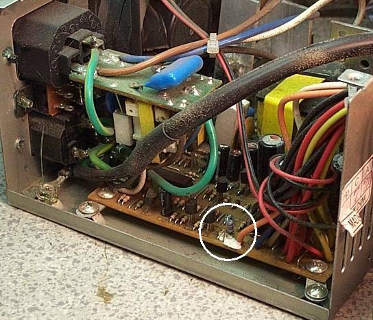
The picture below shows a supply marked PC BY DVE, where the voltage adjustment resistor can be easily identified from the fact that it is mounted vertically, differently from all other resistors that are mounted horizontally. In the picture, one can see that resistor close to the white enamel spot on the printed board, near the orange wire (within the white circle).
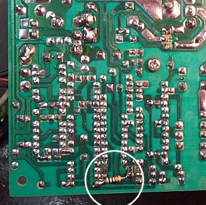
In a supply marked SKYHAWK, I found that the resistance of the voltage control resistor was adjusted, at factory test time, by putting a resistor (on the copper side) in parallel to the basic resistor mounted on the components side. Picture below shows the adjustment resistor, identified by a white circle. Removing that resistor was not sufficient to lower voltage enough, so I had to also change the basic resistor.
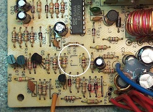
In the case of a supply marked PC BY KME, identifying the resistor was even simpler. You can see, near the center of picture below, the place where a three-pin voltage-adjustment resistive trimmer (marked VR1) was supposed to be mounted (see the white circle). Looking at the copper side of the board, one can see that VR1 is wired as a variable resistor and that the 470 ohm resistor located at its right is in parallel with it. Evidently the original intention was to use a trimmer, but at a later stage they decided to replace it with a plain resistor thar was factory selected.
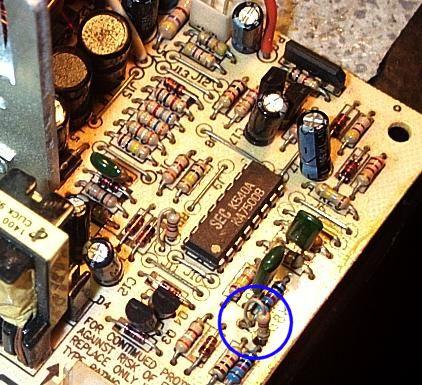
In another supply marked TOP COMPUTER I found a board also built by KME, but different from the one shown above. Nevertheless I again found the three holes for a resistive trimmer (inside the blue circle below), even though in this case they are somewhat less evident. The resistor in between the holes is the voltage adjustment resistor.

Looking at the board of a power supply marked DEC FORMULA, I was immediately attracted by the dark area around the lead entry points of a vertically mounted resistor (see blue circle below). And that was it!
Same approach in a power supply built by the CHUNG LONG METAL CO., which utilizes the quad voltage comparator IC DBL339 and the pulse width modulator IC DBL494, In this case there are five resistors with lead entry points marked dark (see circles in picture below).

By cut-and-try I determined that the resistor at the center of the red circle is the voltage control resistor. I have more than just a feeling that the other four resistors, identified by the white circles, determine the over-current threshold of the protection circuit for the four output voltages, but I have no firm proof of that.
The above examples are only meant to give you a general understanding of voltage adjustment solutions; then it will be up to you to manage your particular case, although tracing the voltage adjustment resistor may not always be easy.
If you use different power supplies, there is a good chance that you will find the way to lower the voltage of at least one of them. So, by working on just one supply and not touching the other ones, you could still be able to obtain the desired total output voltage. An advantage of being able to individually lower the voltage of the three supplies, on top of balancing the load across them, is that the three blowers would so all run at a lower speed, thus decreasing the total noise level.
Generally speaking, when you believe having isolated the voltage adjustment resistor, try putting a resistor of a slightly higher value in parallel to it, and see whether you get a noticeable output voltage variation. If so, you have found the right resistor, and you can then vary it as required, by cut-and-try.
REGULATION
As said earlier, not all supplies show the same regulation (i.e voltage drop under load, in percentage). One of the reasons for the differences is the way each supply takes the reference for the voltage stabilization circuit, i.e. from the +5 V output, or from the +12 V output, or from both, Clearly, best performance is achieved if the supply only utilizes the +5 V output, worst performance if the +12 V output is instead used, and intermediate performance if both are used.
Once you have identified the voltage adjustment resistor for your particular supply, looking at the printed circuit board you should be able to determine whether the reference voltage is taken from the +5 V output, or the +12 V output, or both. In the last two cases, you can do something to improve the regulation of your supply.
As an example I will explain how I improved the regulation of the PC BY KME supplies, that utilize both the +5 V output and the +12 V output as reference voltages. An excerpt of the supply circuit is shown below (the voltage adjustment resistor, marked in red, was changed from 470 ohm to 1,200 ohm so as to obtain the desired 4.8 V output voltage).
I first tried completely removing the 33,000 ohm resistor on the +12 V output, to have the supply only controlled by the +5 V output. Doing so however, the over-voltage protection trips whatever else you do, for reasons still unclear. Then, I decided to just increase the 33,000 ohm resistor and decrease the 11,000 ohm resistor, so as to make the +5 V influence on the voltage control circuit greater, until I found a satisfactory compromise. This is shown below:
The following results were obtained with a 28 A current on the +5V output:
Before modification:
voltage drop on the +5V line: 0.47V
corresponding voltage increase on the +12 V line: 1.37V
After modification:
voltage drop on the +5V line: 0.22V
corresponding voltage increase on the +12 V line: 2.05V
The above hints may help you in tackling your particular case.
SOME EXTRA COMPONENTS ARE NEEDED
When supplies are connected in series, if one supply fails to deliver its voltage for any reason (e.g. a blown fuse), a counter-polarized voltage would develop at its terminals. This condition can damage the supply, and has therefore to be avoided,
The simplest solution is to put a protection diode in parallel to each supply, as shown below.
Please note that, when one supply fails, the residual total voltage could still be high enough to produce a remarkable current in the load. It is therefore recommended that the protection diodes have a rating of 10 A or so. The diodes can be put either internally (as I did) or externally if you prefer so.
Three capacitors (220nF or more) and one electrolytic (2,200 uF or more) have the purpose to eliminate any residual noise.
ELECTRICAL AND MECHANICAL ARRANGEMENT
To put the three supply in series, you shall simply connect, in the appropriate manner, the red and the black output wires. I preferred to make use of all the existing wires (in parallel), instead of cutting some of them out, to reduce the high-current path resistance as much as possible.
I wired the AC male sockets of the three supplies in parallel, so the whole supply can be powered by plugging the AC cord into any of the three sockets (be careful, the other two sockets will have the mains voltage on them).
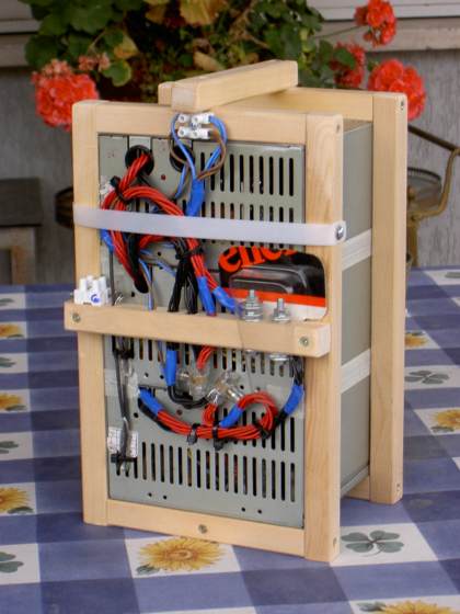
With regard to the mechanical layout, this is left to your fantasy. Picture below shows the way I did it (rushing things a bit).
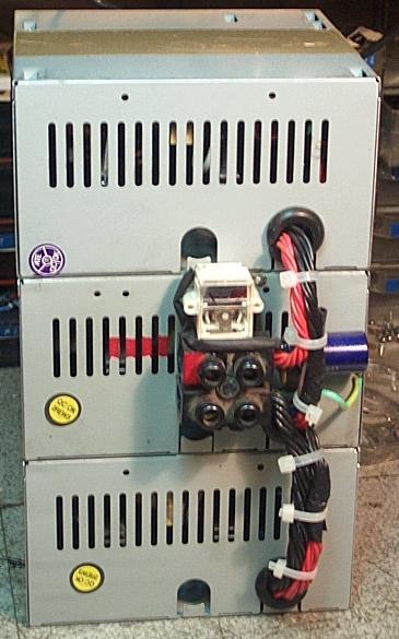
You can see a small meter, in parallel to the 13.8 V output, the purpose of which is to confirm that the power supply is working properly. I do not use an AC power switch, but you can obviously do it.
You can even do a modern sculpture (?) like IKØHIT did...
FINAL TESTS
In my case, I used three AT-style 230 W PC supplies marked PC BY KME. I individually adjusted their voltages so as to obtain the desired total voltage. Feeding my Yaesu FT-100D I get the following values:
The FT-100D voltage specification is 13.8 V plus / minus 10%. So the supply is very well within that.
Note that the DC power consumption is about 300 W, against a nominal total power rating of nearly 700 W.
Return to the I0JX home page