Hi, I am Tony I0JX
Go 6 and 10 meters mobile with your
magnetic-mount 2-meter whip
I never had seriously considered operating HF mobile as, until very recently, we were only allowed to operate in the car on frequencies above 144 MHz. Thus, I just had a Kathrein magnetic-mount 5/8l antenna for 2 meters and a VHF mobile rig. To tell the truth I have not been using that set-up for years...
More recently the law has been changed, and we can now operate mobile on all ham bands, though not while in motion. I was initially tempted to mount a good antenna on my car, but I eventually got scared from having to drill the car body (modern cars have no bumpers...) and to hide cables and wires under the car carpets. On the other hand I have not much time for operating from my car, so a permanent installation would probably be an overkill.
After considering that my main aim was to operate on 6 and 10 meters, i.e. the bands in which a short antenna can still be efficient enough, I decided to study the possibility of using my 2-meter magnetic-mount antenna also on those frequency bands. This perspective led me to buy a small Yaesu FT-100D transceiver.
After some thinking and cut-and-try I succeeded to accomplish my goal, and I then decided to write this page to share my experience with others.
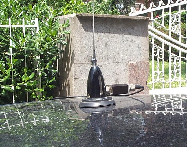
By the way my 2-meter magnetic-mount antenna is a Kathrein model K51 17 2 having a length of 5/8l, but I see no reason why other similar antennas could not do a similar job. You shall however verify that your antenna has no shunt coil to ground (an ohmeter should give infinite DC resistance at the antenna connector), otherwise it would not work on 6 and 10. I am reporting this potential problem because I recently bought another Kathrein antenna marked K51 13 2 (by the way I could not find this number in the Kathrein catalog) which looks identical to model K51 17 2 but has a shunt coil to ground inside. I was anyway able to get it working on 6 and 10, but I had to modify the coil, by removing the shunt to ground and experimentally adjusting the internal inductance.
FIRST OF ALL, WHY A 5/8l ANTENNA ON 2 METERS?
A 5/8l vertical is not extremely short (roughly some 1.3 m), so many people prefer to use the shorter 1/4l antenna (some 52 cm high). But what the differences are between the two?
A first difference is the elevation pattern. Below, you see the gain plot of a 1/4l antenna on the left, and of a 5/8l antenna on the right.
The above diagrams refer to verticals mounted over a real ground, according to the MININEC modelisation (the car top is too small to be an ideal ground, despite it is made of highly conductive material). The 1/4l antenna shows a maximum gain of 3.63 dB over the isotropic at 15 deg. elevation (consider that 3 dB simply stem of the fact that radiation can only occur in the upper hemisphere). The 5/8l antenna has instead a maximum gain of 5.03 dB at 8 deg.elevation. At very low elevations (e.g. 5 deg.), the gain difference goes up to nearly 2.5 dB.
Another difference is the fact that, while a 1/4l antenna is resonant (i.e. it shows no reactive component) and you can then directly attach a coaxial cable to it, a 5/8l antenna shows quite a significant capacitive reactance: this is the reason why those antennas have a series-coil at the bottom resonating the capacitance (in the Kathrein antenna the coil is housed within a black plastic enclosure). Doing so the 5/8l antenna offers a good match to a 50 ohm cable, as well as the 1/4l antenna. Reason for the capacitive reactance is that 5/8l is a length a bit shorter than the closest resonating length, i.e. 3/4l. Why then not using a 3/4l antenna that would be just some 20 cm taller? Looking at the elevation pattern of a 3/4l antenna you will immediately understand why.

A lot of difference: the 3/4l antenna has a a maximum gain of 6.29 dB, but at 47 deg. elevation, this meaning that the antenna mainly radiates to the sky, not to where you want to.
NOW, LET'S START BY ADDING 6 METERS
The Kathrein magnetic-mount antenna is to be trimmed for resonance at your preferred 2-meter frequency by cutting the rod bit by bit; I did this many years ago and I have now measured that it is 124.5 cm long (from the rod tip to the top of the plastic base).
It is easy to calculate that 124.5 cm is not terribly far away from a 1/4l at 50 MHz; actually it seems a bit too short, so the antenna should show some capacitive reactance at that frequency, though the coil inside the antenna base will partly compensate for it. In practice, the resonant frequency of the antenna occurs just a bit too high in frequency, but the SWR at 50.1 MHz is low enough to be directly usable at that frequency.
I then accidentally found a Kathrein data sheet which I had probably since some 30 years. Look at the diagrams.

Operation on 6 meters as a 1/4l antenna was already envisaged by Kathrein themselves! They measure the antenna height including the plastic base which is exactly 10 cm high, so my length of 124.5 cm corresponds to 1,345 mm on the above graphs. Coincidence is perfect on 2 meters, but on 6 meters the graph gives a resonant frequency lower than 50 MHz for that length, whilst SWR measurements taken with a Bird wattmeter indicate a resonance above 50 MHz, as already mentioned. In conclusion, things may vary depending on the particular installation, so, before doing anything, you better measure the resonant frequency on both bands and only then decide what to do.
Though not actually needed, I then decided to obtain a really perfect match around 50 MHz by increasing the rod length by 5 cm centimeters, so bringing the total antenna length up to 129.5 cm (the actual value may however vary somewhat depending on your particular antenna and installation). I did this by fastening a piece of copper wire to the tip of the antenna rod, by means of a small screw-on electrical connector (remove all plastics around to decrease wind load). Should I want to operate on 2 meters, I can easily remove the extra length, by unscrewing the screw-on connector.
THE CHALLENGE: GOING TO 10 METERS
The antenna can be resonated on 10 meters by means of a suitable L-C matching network. Due to the difficulty of going cut-and-try when working on a car, I preferred to firstly measure the antenna impedance, such as to able to pre-calculate the values of the required matching network.
To do this I asked a senior antenna engineer at Space Engineering to help me measuring the Kathrein antenna impedance in the frequency range of my interest. Below you see Alessandro performing measurements using a Wiltron network analyser.

You obviously need a cable to connect the network analyser to the antenna, nevertheless that instrument still permits to determine impedance at the antenna connector. This is possible because the analyser supports a calibration procedure intended to assess the characteristics of the cable run being used, and then, once the impedance transformation operated by the cable is calculated, it automatically adjusts the impedance measurement taken at cable end and directly gives you the impedance at the antenna connector.
The measurement cycle actually consists of four steps:
The following graph shows how the measured resistive and reactive impedance components of the 129.5 cm antenna vary in the 45 - 55 MHz range.
Actually, the antenna appears to resonate at 49 MHz, i.e. a bit lower than what determined on the basis of SWR measurements (it is however not easy to very precisely measure resonance just looking at SWR). The antenna resistance at 49 MHz is 52.6 ohm, such value causing an SWR of 1.01 on 50-ohm cable. At 50.1 MHz the SWR grows up just a bit.
The following graph shows how the antenna behaves in the 24 - 34 MHz range.
As expected, at 28.3 MHz the antenna is capacitive, but its resistance is not terribly low as one may expect, and that is important for good matching efficiency. As a matter of fact Z = 17.2 - j 262.0
Attaching a 50-ohm cable directly to the antenna would cause an excessive SWR mainly due to the reactive component, therefore a matching network is needed. My preferred way is to have that network located directly at the antenna connector rather than at the other cable end.
Firstly, I have calculated the matching network values for 28.3 MHz, as shown below:
Then I have built the network in a small metal box having a female and male UHF connector.

I calculated the inductor parameters using formulas that can be found in the Radio Amateurs' Handbook. There are 13 turns of teflon-insulated silver-plated 1 mm-diameter wire around a 12 mm-diameter plastic form. A ferrite core permits to adjust inductance for minimum SWR. The 150 pF capacitor is instead fixed.
The box is attached directly to the antenna connector, as shown below (it must obviously be removed for 6- and 2-meter operation).
Amazingly, the circuit worked immediately and, turning the ferrite core, the SWR on 10 meters went down to nothing. Subsequently, I changed the matching network design, using a fixed coil and a variable capacitor, but this does not change the substance..
After trasmitting for some time, the inductor becomes a bit warm, this fact indicating that ohmic losses are quite limited.
I experienced RF feedback problems (distorted voice) probably due to some RF on the cable braid, but it was easy to cure them by winding RG-58 coaxial cable over a nearly circular form consisting of four 10 mm-diameter 15 cm-long ferrite rods kept together by scotch tape. This coil is located inside the car, close to the point where the cable gets out. In practice, you shall use a cable run longer than strictly needed, and wind part of it on the ferrite form.
First QSO was UN0LE (59) followed by a great deal of other DX stations in all continents. My conclusion is that I can work all signals I can hear; clearly, if there is a pile up, things become more difficult.
Plot below shows the elevation pattern at 28.3 MHz computed by EZ-NEC, which gives a gain of 4.1 dB at 13 deg. elevation. But one may not just trust that figure, as ohmic and ground losses have to be accounted for (the 17.2 ohm value is too high to only be radiation resistance...). I reckon that the antenna gain could range some -1 dB with respect to the isotropic.
EVEN MORE CHALLENGING: TRY 12 METERS
In principle, the Kathrein antenna could also operate reasonably well on 12 meters. If you wish to try that too, please note that, at 24.9 MHz , Z = 23.3 - j 318.6
The resistance value of 23.3 ohm is higher than on 10 meters, whilst it should be lower. This probably means that, on 12 meters, ground loss becomes even greater.
The required matching network would be:
I did not test it, so play with it if you wish!
By the way, you may be interested to also see my page on short antennas; if so, go to http://www.qsl.net/i0jx/antenna.html or http://www.geocities.com/gvernucci/antenna.html
Drive safely...
Return to the I0JX home page