
Hi, I am Tony I0JX
Geloso: an important
Italian contribution to ham radio
Ham radio equipment schematic diagrams are at end of page
John Geloso was born in Argentina January 10th 1901, where his Italian parents had temporarily moved from Italy. The entire family moved back to Savona Italy in 1904, where John studied at the nautical school. After finishing school John started an electromechanical workshop where he manufactured items he had personally patented. In 1920 he went to the U.S., and began working for Pilot Electric Manufacturing in New York and attending Copper Square University. After graduation, in 1925 he was appointed chief engineer by the Pilot president Mr.Isidor Goldberg who had realized the potentiality of that young Italian.

John was able to solve most of the problems affecting, at that time, the development of radio, such as receivers AC supply, single command for frequency change, acoustic improvements, etc.
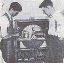
In 1928, in front of several scientists among which Lee De Forest (the "father of radio") and Hugo Gernsback (the licensee of the WRNY station), he demonstrated a system for images reproduction based on a Nipkow disk with 44 holes, able to generate 36 lines and 15 frames per second. Images were transmitted from a transmitter site at Hudson Terrace in Coytesville (NJ) to Philosophy Hall (NY), on the wavelength of 326 meters, since pictures could not be properly synchronized through the WRNY Hotel Roosevelt studios. Reception required a 24 inch scanning disc rotating at 240rpm. Eventually, Gernsback presented daily 5 minute programs in cooperation with John Geloso, via 48 line mechanical scanners set up in Coytesville,
Below you can see John (on the left hand side) with his telecinematographic equipment.
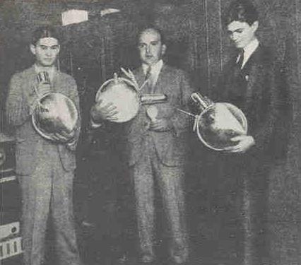
Here John holds one of the early photocells used for television purposes, in company of Hugo Gernsback (center).
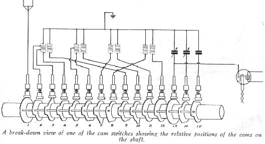
By 1929 he was deeply committed to the design of the Pilot Super Wasp receiver, the first completely AC-operated short-wave receiver in the market. John was mainly interested in the mechanical aspects of replacing plug-in coils, commonly used at that time to achieve multi-band operation, with a mechanism of highly ingenious construction based on switches operated by cams.
In 1931 he returned to Milano, Italy for setting up its own business.

The first Geloso radio I am aware of is model G.50, dated back to 1932. It had five tubes, i.e. two RF amplifiers (UY235), one detector (UY224), one audio power amplifier (UY247) and one rectifier (UY280).
At that time home radios were fairly pricey compared to an average wage and, to save money, it was then common to buy apparatuses in kit form (most commonly NOT including a wooden cabinet, which one often had to construct by himself...).
Some excerpts from the G.50 presentation:
" ... often some instability phenomena can occur... (some guidance is then given on how to avoid instability) ... but if the radio is too stable, then it will also be not too sensitive ..."
" ... hum will totally disappear increasing the capacitor up to 8 microfarad, and this will be possible when electrolytic capacitors will become available ..."
"... our sole ambition is to get soon all necessary materials and components ..."
Looking at the G.50 schematic diagram, one can see that, while paper capacitors were measured in microfarad as done today, the RF capacitors (i.e. the mica and the variable ones) were measured in centimeters (cm). Farad belongs to the MKS measurement system, and centimeter belongs to the CGS system. Below you see the label of a 5,000 cm transmit mica capacitor of those years.
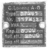
After some search, I have determined that 1 cm is equal to about 1.1 pF, therefore the 5,000 cm capacitor actually has a capacitance of about 5,500 pF.
By the mid-30ies, John Geloso S.A. had already become an important home and professional electronics manufacturer, representing one of the few alternatives to importing equipment from abroad.
Geloso was also building plain components, such as switches, capacitors, potentiometers, transformers, etc. (really made in Milan, not re-labeled Taiwan stuff...); on the other hand autarky was one of key guidelines in the fascist era.
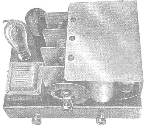
Geloso was also active in the military field, as witnessed by this odd circa-1935 transceiver working in the 50 - 56 MHz range.
![]()
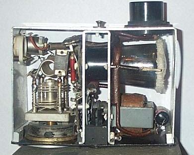
The front panel is marked (in Italian) "Small radio box - companion to a m/m-180 photophonic station". Before WWII "photophonic" stations were used for short-range voice and "optical telegraphy" communications between the military underground fortifications of the Alpine Wall, over a light beam that the enemy could hardly intercept. The radio link was alternately used in case of fog or obstacles degrading the optical link quality. The small transceiver employs a 4-volt direct-heating tube (a Zenith type RRBF, built in Italy by FIVRE) working either as super-regenerative receiver or as self-oscillating transmitter (AM + FM at the same time). Despite its low RF output power (around 250 mW) and its very broad and deaf receiver, I succeeded to work Trevor G3ZYY in Cornwall UK on 50.370 MHz FM with fairly good signals, profiting of a sporadic-E opening. Interesting to note that the RX/TX switch only changes the grid resistor value, absolutely nothing else!
In 1934 the Geloso factory moved from its initial site of via Sebenico 7 to a new site in via Brenta 18 still in Milano, and in 1939 to a large plant in via Brenta 29 (about 17,000 square meters).

After WWII, Geloso expanded the production of components (electrolytic capacitors, microphones, piezo pick-ups, pre-adjusted receiver RF groups, IF transformers, etc.) as well as of complete equipment, including a wide selection of radios, audio amplifiers, recorders, vinyl disk players, etc.
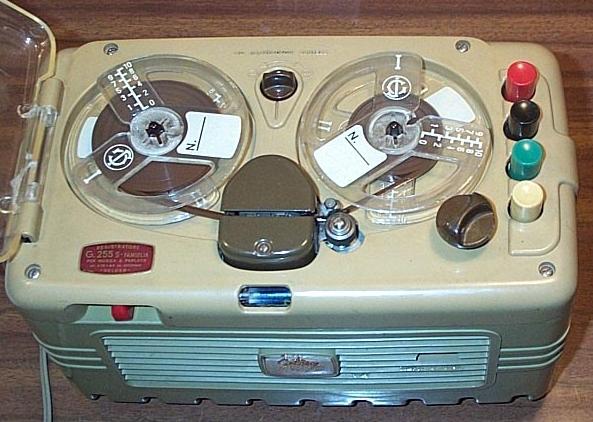
Surely, the most popular Geloso product was the tape recorder mod. G.255 which was introduced in 1957. Most Italian families owned one of these.
Another important product line for Geloso were TV sets, B&W of course. At that time they came in just a few screen sizes, i.e. 17", 21" and eventually 24". The price of a TV set was rather high; the console model shown below costed 330,000 year-1954 lira, that correspond to about 4,100 year-2001 Euro (currently 1 Euro is about the same as 1 US $).
Designing TV sets was not always an easy task at that time. Look at the solution that they had to adopt for getting the proper coupling factor between the sweep generator tube and the mixer tube. The screen of a 9-pin miniature tube was modified to derive a signal of an appropriate level.
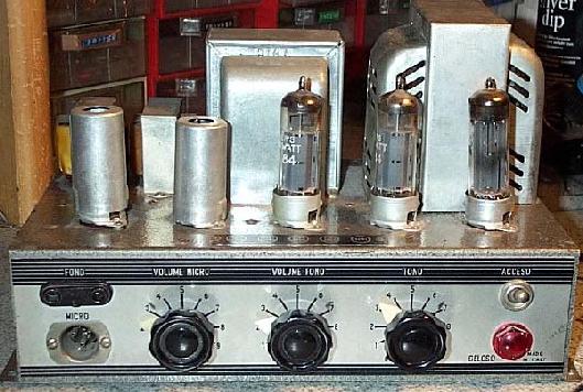
Below, you see a 75-100W amplifier (model G.274/A) which was used by I0APV, around 1950, as a modulator in his AM transmitter using a single PE1/100 in the final stage.
The G.274/A has a push-pull pair of 807s driven by a 6L6G. Two pre-amplifier stages with 12SL7s. A 5R4GY and a 5Y3GT are used as rectifiers. The output transformer (Geloso mod. 6054) had been replaced with a modulation transformer (Geloso mod. 6055) that has the appropriate output impedance for modulation purposes.
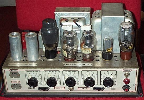
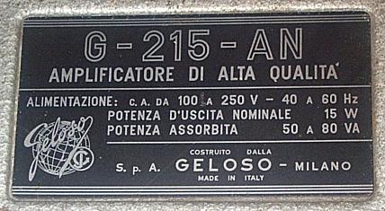
A decade later the Geloso audio amplifiers had a bit more modern appearance, see model G.215-AN, donated by Joe I0AWJ, using a push-pull pair of EL84s for a nominal output power of 15 W.
Yes, at that time manufacturers were still serious and declared real power, not the odd things we see today like "instantaneous peak musical power". Would you believe I recently saw a car amplifier using two EL84s, built for nostalgic hi-fi aficionados, advertised as a 200 W amplifier? Geloso did not even dare to use the "high-fidelity" term, so they just called it "high-quality amplifier".
All components were made by Geloso, even capacitors, switches and connectors. Look at those brown matchbox-style electrolytic capacitors.
Geloso, who had a radio amateur license with call I1JGM, began an ham radio products line in 1952 with the first ham bands-only professional receiver, the G. 207, which was produced in three versions, i.e. G. 207-AR, G. 207-BR and eventually G. 207-CR.
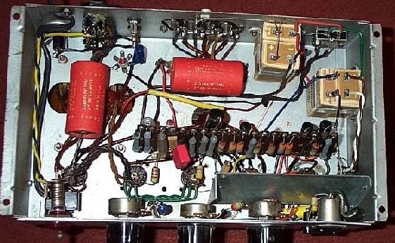
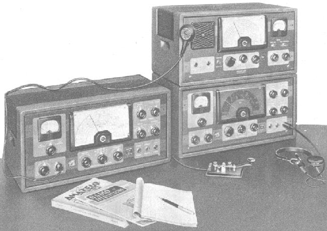
In 1955 the first "Geloso line" was born, by pairing a G. 207-CR receiver to the G. 210-TR transmitter (using a single 807 modulated by a push-pull pair of 6L6Gs). Picture below shows the G. 210-TR (left), the G. 207-CR (right), with a G.208-A general shortwave receiver on its top.
Look at the G.210-TR interior.
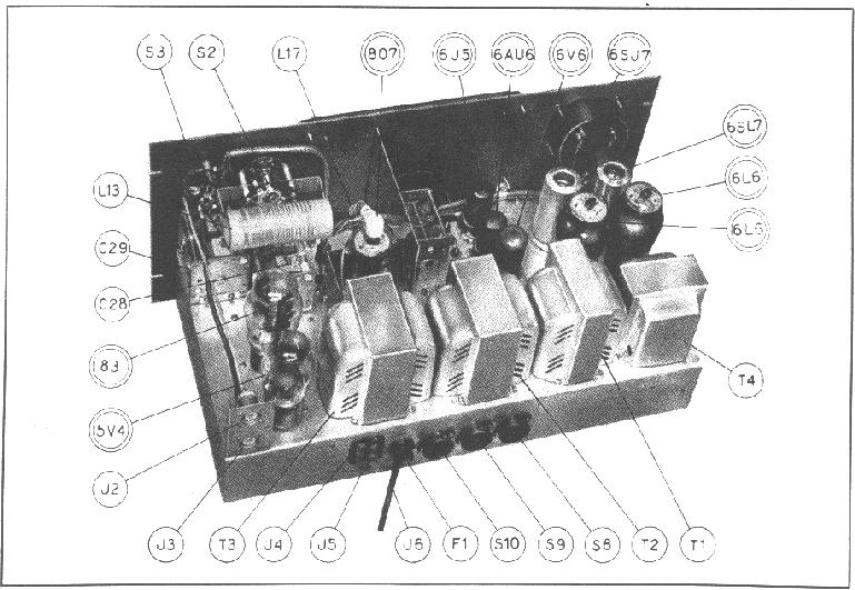
The G.210-TR transmitter included the very first Geloso Variable Frequency Oscillator, i.e. the VFO mod. 4/101. Note that the tube marked 6AU6 looks to be an octal tube instead of a miniature one, as it should be. The above picture was probably taken before they decided to change that tube (an 6SJ7?) into the more modern and better performing 6AU6.
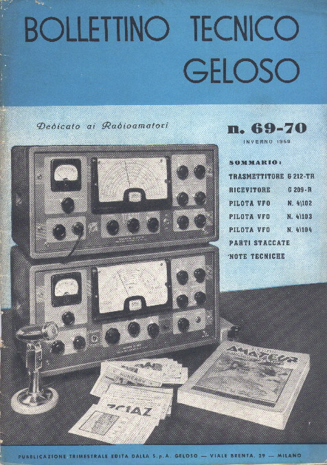
In 1958 a new line came out, i.e. the G. 209-R receiver (153,500 year-1958 lira, or some 1,650 year-2001 Euro) and the G. 212-TR transmitter (125,000 year-1958 lira + 395 lira of "tube taxes", for a total equivalent of some 1,350 year-2001 Euro), still having a single 807 in the final producing 40 W RF, but now with a pair of 807s for modulation.
Picture below shows the cover page of the Winter-1958 "Bollettino Tecnico Geloso" describing both the G. 209-R and the G. 212-TR. The Bollettino was published several times per year since 1932, and contained a very detailed description of new products (in many cases it constituted the instruction manual).
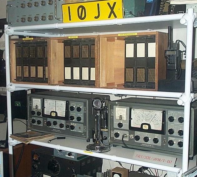
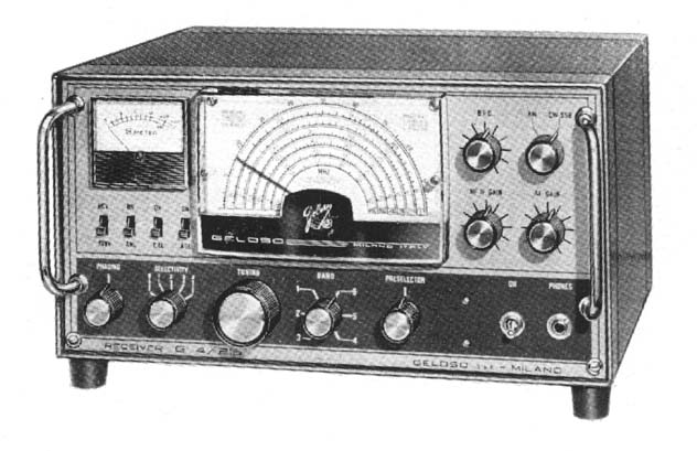
In 1962 the last AM/CW-only line appeared: on the left-hand side of picture below you see my G. 4/214 receiver (double conversion superhet for AM, CW and SSB, but rather poor on SSB due to its limited frequency stability, the absence of a product detector and the lack of a fast-attack slow-decay AGC) and, on the right-hand side, my G. 222-TR AM/CW transmitter (60 W RF produced by a single 6146 modulated by a push-pull pair of 807s). Still today, I use this equipment with satisfaction mainly on the 10-meter AM segment (29.0 - 29.1 MHz): lot of US contacts!
In 1964, an improved transmitter version appeared (the G. 223-TR), similar to the G. 222-TR but featuring higher frequency stability by the use of a conversion-type VFO (mod. 4/105).
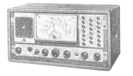
By the way, the ham-radio equipment case was also used for other purposes; below you see model G.1523C, an odd integrated audio amplifier / broadcast receiver / switchboard specifically designed for airports, railway stations, jails (hi), department stores, churches, etc.
All the main items constituting Geloso receivers and transmitters were also individually sold, so that one could easily build an home-made transmitter using a Geloso VFO, a Geloso tank coil, a Geloso RF choke, Geloso variable capacitors, Geloso crystals, Geloso transformers (power and modulation), and an home-made receiver using a Geloso "RF group" (everything down to a 4.6 MHz IF), Geloso IF transformers, etc. etc. Interesting to note that, who knows why, Italian amateurs using Geloso equipment, when declaring their working conditions, used to replace the word "Geloso" with then term "la nota casa" (i.e. "the renowned factory").
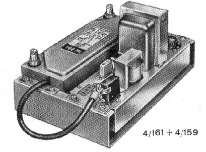
In an period when people were much more budget-minded than today, readily offering the most critical equipment building blocks made Geloso very popular among amateurs, even in the U.S. where many hams still today have Geloso equipment or parts hidden somewhere in the basement. At this regard it should be noted that, in 1963, Geloso introduced, as part of his line of nuvistor-based VHF converters, models operating on bands at that time only available to U.S. amateurs (mod. G. 4/160 for 50 - 54 MHz and mod. G. 4/162 for 220 - 224 MHz). It is also interesting to note that the Bollettino was bi-lingual, Italian and English: though this would be normal today, it was not so in the 50ies when only a small percentage of the Italian population had some command of the English language. These facts witness that Geloso was aggressively hitting the U.S. market too.
See the 144-MHz nuvistor converter (model G. 4/161) hooked up to its power supply (G. 4/159)
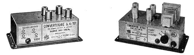
and the older ones with conventional miniature tubes viz model G. 4/151, and model G. 4/152 which had a built-in power supply and costed 38,325 year-1966 lira, or some 310 year-2001 Euro.
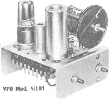
The most popular Geloso loose item surely was the VFO for the HF range (10 through 80 meters). The early model was the 4/101, used in the G.210-TR transmitter, with a 6J5GT oscillator, a 6AU6 doubler / buffer and a 6V6GT driver.
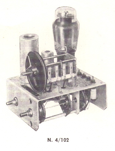
It was soon followed by model 4/102, in which the 6V6GT was substituted by a more powerful 6L6G, this change making it possible to drive two final tubes (e.g. 807s) in parallel instead of just a single one.
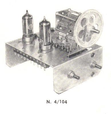
The later model 4/104 instead had just two tubes, a 6CL6 oscillator and a 5763 driver, both miniature. This VFO, which was intended to drive a single tube (e.g. one 807 or 6146), appeared for the first time in the second Geloso transmitter (the G. 212-TR).
In reality, quality was not the best one could expect: switches often suffered from unstable contacts, VFOs were generally quite unstable (even the most recent VFO, the conversion-type mod. 4/105, was not a real rock...). At this last regard, it is interesting to note the solution that Geloso adopted for his VHF VFO (144-MHz), the model 4/103.
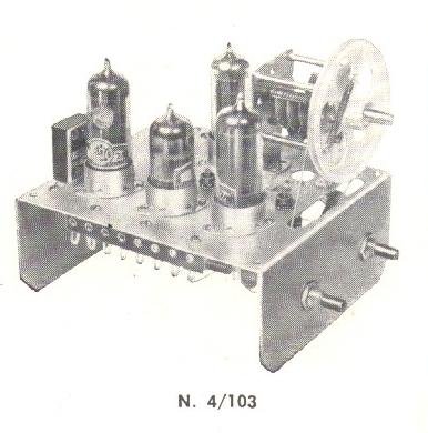
Actually model 4/103 incorporates two completely separate oscillators (two 6CL6s), that is a crystal one and a free-running one (i.e. a proper VFO). A 12AT7 is used to switch the two signals and a 5763 to drive the power amplifier. Below, I report how the summer-1962 issue of the Bollettino justifies the need for two oscillators:
"The aim of having two different oscillators, the VFO type and the crystal type, is that of using the former for brief connections (for the research of a correspondent, etc.), and the latter (having a greater frequency stability) for a normal connection."
To better understand this, one should remember that at that time (at least in Italy) 144-MHz operations were normally crystal-controlled (each amateur in a local area could easily be identified just by his transmit frequency). So, breaking in an on-going QSO was an almost impossible task, as neither of the two hams in QSO would have his receiver tuned on the breaker's transmit frequency. Geloso offered a solution to this problem: using the VFO-type oscillator one could quickly break in the QSO and tell one of the two guys: "Please listen for me, I am on 144.900!"; then, by means of the crystal-type oscillator, he could continue the three-way QSO with better frequency stability.
Coming back to the Geloso lines, the SSB era began in 1965 with the G. 4/225 transmitter (222,000 year-1965 lira, or some 1,825 year-2001 Euro). The transmitter, having a separate power supply (the massive G. 4/226 at 77,000 year-1965 lira, or some 650 year-2001 Euro), adopted phasing-type SSB. In addition to other more common tubes, it used a parallel of 6146s delivering 100 W RF out, three (today hard-to-find) 7360s as balanced modulators, one 6CW4 nuvistor as crystal oscillator, and even an EM87 ("magic eye") to permit properly adjusting the transmit audio level! The case size was still the same as that of the ancestral G. 207 receiver so, in total, you had to accommodate three real beasts in your shack. See two of them below (transmitter and matching power supply)
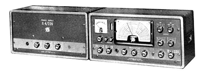
The new companion G. 4/215 receiver, shown below, was only produced for a short period and is therefore rather hard to find.
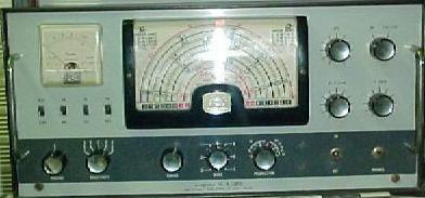
Its more modern case, as well as the new panel colors, were an early sign that Geloso was going to re-style their ham-radio products. As a matter of fact the G. 4/215 receiver was soon after replaced (in 1967) by a new receiver, the G. 4/216, having a smaller case.
The G. 4/216, paired to the new G. 4/228 transmitter having three 6146s in parallel, was the very last Geloso ham-radio line, Despite the smaller case, the three pieces (the G. 4/228 had an external supply, the G. 4/229, all having the same case of the G. 4/216) still occupy a remarkable room on your desk. Noticeably this line, as well as all the former ones, had no transceive facility, and you so had to zero-beat the transmitter each time.
The company went out of business in 1972, four years after John Geloso death.

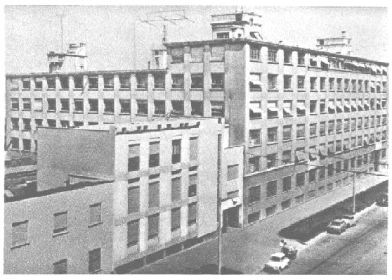
Their former headquarters located in Milan via Brenta 29 is now owned by a bank. Picture below was taken before 1960.
After 1972 however Geloso equipment were still on the market because the trade mark was acquired by other companies, which continued producing equipment marked Geloso. Below you see a 50-W FM broadcast transmitter (with a push-pull pair of 6146B in the final) marked Geloso, but built and marketed by PASO S.p.A., a company also located in Milano.

The rationale behind this product is that, around 1975, there was a huge demand in Italy for FM-radio transmitters, as almost anyone could freely set-up and operate his own broadcast radio, the applicable laws being unclear (or perhaps just not enforced?).
By the early 80ies the Geloso trade mark was still used to label cheap electronic stuff produced in the far east.
By the way, I forgot to tell you that "geloso" is the Italian for the English word "jealous".
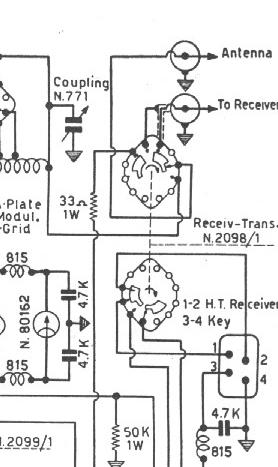
Going back to my Geloso line, I wish to report you on some of the design oddities which I found in the G. 222-TR transmitter schematic diagram. First of all, believe it or not, the front-panel receive / transmit switch (as well as the receive / VFO-beat switch) operates directly on the 220 VAC line; in other words transformers get only powered when one transmits or wants to zero-beat! Real energy saving, isn't it?
With such an arrangement, switching back from transmit to receive one would hear a carrier in his receiver until the power supply capacitors have discharged. To avoid this, the transmit / receive switch was designed in such a way that, just at the very middle of its excursion, a resistor was temporarily grounded to quickly discharge the electrolytic capacitors. This excerpt of the schematic diagram witnesses that I am not joking: you can see a 33-ohm 1-W resistor, connected to the power-supply electrolytic capacitors, getting shorted to the braid of the coax coming from the receiver socket.
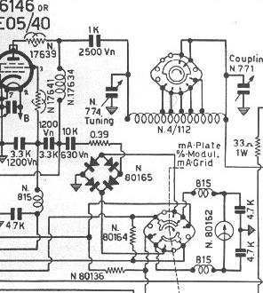
Another candy. The front-panel meter can conveniently be switched to measure either plate current, or grid current or AM-modulation percentage, but in the plate-current position the meter is directly inserted in the high-voltage line, this meaning that the whole meter (and the switch) is at 750V potential. Don't worry: the plastic meter lid will protect you anyway... Here it goes: the resistor marked N. 80164 is the meter shunt through which plate current flows.
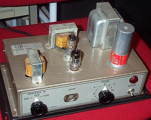
Before leaving this brief tour, please give a quick look to my Geloso G. 299 (1958), an unusual equipment called "Oscillofono" having the very plain task of generating an audible tone on pressing a Morse key (a loudspeaker was not included). This unit was expressly designed for code training; I guess it is a pretty rare item. In kit form, its year-1958 price was 13,500 lira (without tubes), equivalent to about 150 year-2001 Euro.
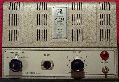
By means of a front-panel switch one can select the tone frequency, either 800 Hz, or 1,000 Hz or 1,200 Hz. The socket marked "Tasto" (the Italian for "Key") mates to the typical Geloso 3-pin microphone plug. The audio output on the back panel has two impedances, 3.2 and 600 ohm. The output waveform looks very good on the scope, a nearly perfect sinusoid.
What that sturdy box does can today be done by just a tiny NE555 plus, if you really need more power, an audio-amplifier IC. The G. 299 instead includes:
The world was much simpler than today, but we enjoyed it anyway, didn't we?
Geloso ham radio equipment
Notes:
downloads are in GIF format
Receivers:
| Schematic Diagram | RF Group no. |
Dial Scale no. |
Described in Geloso Bullettin no. (courtesy of IW2DGS) |
| Receiver G. 207-R | 2606 2606A 2607 | 1641 | 52-53 54 |
| Receiver G. 207-AR | same as G. 207-R? | - | |
| Receiver G. 207-BR | 2606E 2607 | 1641 | 58 |
| Receiver G. 207-CR | 2606E 2607A 2616 2616A | 1641 | 59-60 |
| Receiver G. 207-DR | 2607A 2617 | 1641 | 66 |
| Receiver G. 209-R | 2618 2618A 2619 2619A 2620 |
1643 1655 |
69-70 83A |
| Receiver G. 4/214 | 2608A 2620A | 1655/A | 85 |
| Receiver G. 4/215 | 2625 | no number | 96A |
| Receiver G. 4/216 | 2626 | no number | 103 |
Transmitters:
| Schematic Diagram | VFO no. |
Dial Scale no. | Described in Geloso Bullettin no. (courtesy of IW2DGS) |
| Transmitter G. 210-TR (one 807) | 4.101 | n. 1640 | 47-48 59-60 |
| Transmitter G. 212-TR (one 807) | 4.104 | n. 1646 | 69-70 |
| Transmitter G. 222-TR
(one 6146) 2nd series (starting serial no. 6001) |
4.104 | n. 1646 | 83A 85 |
| Transmitter G. 223-TR (one 6146) | 4.105 | n. 1657 | 95 |
| Transmitter G. 4/225 + G. 4/226 (two 6146) | 4.192 | ? | 96 |
| Transmitter G. 4/228 + G. 4/229 (three 6146) | 4.193 | ? | 105 |
| VFO for HF transmitter with one 807 | 4.101 | n. 1640 | 49-50 |
| VFO for HF transmitter with two 807 | 4.102 | n. 1640 | 69-70 |
| VFO for VHF transmitter with one 832 or two 2E26 | 4.103 | n. 1647 | 69-70 |
| VFO for HF transmitter with one 807 or 6146 | 4.104 | n. 1646 | 69-70 |
| VFO for HF transmitter with one 807
or 6146 (conversion type) |
4.105 | n. 1657 | 95 |
Converters:
Return to the I0JX home page