Hi, I am Tony I0JX
Connecting a DFD2-S Digital Display
to a Collins 75S-series Receiver
1 The DFD2-S Digital Display
The DFD2 is a digital frequency display produced by AADE in various flavors, and intended for old tuned-IF receivers. I bought the core board (with no enclosure) customized for Collins 75S-x receivers in kit version at a reasonable price (model DFD2-S, see http://www.aade.com/dfd2.htm). I also bought the biggy backlit display option (http://www.aade.com/biglcd.html), which is comparatively fairly expensive, but very nice and highly recommended. AADE also sells a full-featured plug-and-play wired version of the display called C75S (http://www.aade.com/C75/C75.htm), having the DFD2-S housed in a nice looking box and including the TCXO Reference Oscillator option (http://www.aade.com/dfd.htm#tcxo), as well as the biggy display. I did not buy the C75S mainly because, in my particular case, having a separate display box would not have been handy.
The DFD2-S kit is easy and quick to build, no special comment about that. Please note that I have selected a value of 18 ohm for the resistor feeding the biggy backlit display (from the regulated 5VDC), that value producing the proper brightness (to my opinion).
One of the nice features of the DFD2-S is that it also displays the operating mode (USB, LSB, CW), determining it from the receiver Beat Frequency Oscillator (BFO) frequency (the BFO is one of the signals that are fed to the DFD2-S). When the receiver is in the AM mode there is obviously no BFO, and the display has been programmed so as to show AM when it sees no BFO signal.
To show the receive frequency, the DFD2-S must also be fed with the receiver Variable Frequency Oscillator (VFO) and High Frequency Oscillator (HFO) signals. The BFO, VFO and HFO signals are appropriately summed/subtracted within the DFD2-S so as to accurately reconstruct the 75S-x receive frequency. In the AM mode, the DFD2-S, seeing no BFO signal, simply applies a 455 kHz software bias. In the CW mode, the latest DFD2-S version also compensates for the tuning shift needed to obtain an audio tone out of the CW carrier.
The DFD2-S works very fine. As I had to spend a little time to make it work properly in conjunction with my 75S-3B receiver, Ithen thought that those also wanting to use that display could be interested in my experience.
2 Preparing the DFD2-S interconnections
AADE provides instructions on how to interface the DFD2-S display to either a 75S-x receiver or a KWM-2 (http://www.aade.com/applications/C75.htm). Such interface consists of:
a DC cable, by which the 75S-x provides the required DC voltage to the the DFD2-S module;
a coaxial cable, feeding the receiver HFO signal to the DFD2-S;
a coaxial cable, feeding the receiver VFO signal to the DFD2-S;
a coaxial cable, feeding the receiver BFO signal to the DFD2-S.
Said cables can be passed through a hole located on the receiver back panel. The way to connect the DC cable is explained in Sect. 3. The HFO and VFO cables are to be connected to two existing RCA sockets located on the receiver chassis (as explained in Sect. 3). The BFO cable must be connected to a BFO RCA test socket that some receiver versions are reported to have; if your receiver does not have such socket (like in my case) proceed as described in Sect. 3.
Instructions are rather concise, and do not dwell much on the issue of interconnecting both a DFD2-S and a 32S-x transmitter (for transceive operation) to a 75S-x receiver. At this regard, it should be noted that both the DFD2-S and the 32S-x take the same HFO and VFO signals from the receiver. What I did is to go step-by-step, initially only hooking up the DFD2-S to my 75S-3B receiver, after disconnecting my 32S-3 transmitter. Once the DFD2-S was shown to work properly, I then passed to also connect the transmitter.
3 Connecting the DFD2-S to a 75S-x receiver
After building the kit and having fully disconnected the transmitter from the receiver, I began connecting the DFD2-S board to the receiver, closely following the instructions.
With regard to the HFO and VFO signals, I just plugged the two coaxial cables coming from the DFD2-S into the appropriate receiver RCA sockets (marked XTAL OSC OUTPUT and VFO OUTPUT respectively).
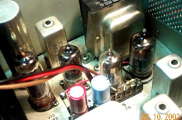
As to the BFO, my receiver does not have the BFO test socket, so I followed the AADE suggestion to take the BFO signal by means of wire eyelet over pin 8 of V8, to which the coaxial cable coming from the DFD2-S is to be connected.
Finally with regard to the DC cable, I made another similar wire eyelet over pin 4 of V8, to take the 6.3VAC filament voltage which I had considered sufficient, once rectified by means of a diode and a 1000uF capacitor, to produce enough DC voltage for feeding the DFD2-S (to my opinion, such arrangement is simpler that taking the filament voltage directly from the power connector as AADE suggests).
Despite I fabricated the two eyelets with maximum care, and wrapped the wire as tight as possible around the tube pin, I immediately realized that contacts were unreliable. Wrapping two turns instead of just one improved the situation a lot, but in the end I decided to open the receiver and solder wires directly on the V8 socket.
After hooking up the DC cable and the three coaxial cables, the DFD2-S immediately began working, but with receiver in the AM position the frequency reading was wrong and unstable, and the mode indication was random. After some investigation I realized that the 5VDC voltage produced by U6 (the 78L05 regulator IC) was affected by a significant ripple. It was easy to determine that such problem was due to a low input voltage to the regulator. Probably the fairly high current (about 65mA) drawn by the backlit biggy display contributes to that.
The easy solution was to use a voltage doubler rather than a simple half-wave rectifier. The circuit shown below produces about 12VDC under load.
Using that circuit all problems disappeared and the frequency reading was perfect and stable in the AM mode too. The voltage doubler is supported by a contact strip that I have mounted close to V8 (note that the mounting screw does not luckily have a nut below the chassis, so you can unscrew it with no problem). The strip also supports the coaxial cable picking the BFO signal.
While playing with the receiver, I noted a very strange effect: in the AM mode the frequency reading was changing somewhat depending on the strength of the received signal!!! Furthermore, in presence of a strong signal, the mode indication was occasionally changing from AM to USB or perhaps LSB or CW. This phenomenon was not apparent in modes other than AM. To better understand this unexpected effect, I disconnected the antenna from the receiver and activated the receiver calibrator which produces a strong, clean and stable carrier. By turning the preselector knob I could vary the strength of the calibrator signal, and observe the frequency reading changing within a total range of a few hundred Hz, and the displayed mode sometimes switching from AM to something else.
Looking at the receiver schematic diagram it was easy to determine the reason for such odd behavior. Picture below shows an excerpt of the 75S-3B schematic diagram.
In the USB, LSB and CW modes, V8B produces the BFO signal which, through L12 and C100, reaches the Product Dectector cathode (V8A), from where the signal feeding the DFD2-S is also taken. Within V8A the BFO signal beats with the 455 kHz IF signal, and the detected audio signal appears on the V8A plate.
In the AM mode V8B gets interdicted and no BFO signal is then present on the V8A cathode (and then on the DFD2-S BFO input) any longer. In such conditions V8A acts as a cathode follower, so leaking the 455 KHz IF signal into the DFD2-S BFO input. So, a strong IF signal will get processed by the DFD2-S, causing it to vary the frequency readout for some reason.
A simple solution to the problem was to not directly connect the V8A cathode (pin 8) to the DFD2-S BFO input, but to do it via a 10-kohm resistor (which can be seen in the above picture), and to put another 10-kohm resistor in parallel to the DFD-2S input protection diodes. The input BFO signal reduction caused by such voltage divider is well tolerated by the DFD2-S, while the leaking IF signal is brought down to such a low level not to cause problems. AADE mentions that reducing the input signal level could be appropriate in some cases, but they cite reasons different from the one reported above. Furthermore, to do that, they suggest to put just a resistor in parallel to the input diodes, while I prefer to also use a series resistor so as to reduce the load that the display circuit inevitably causes on the BFO, HFO and VFO lines.
At this regard, by quickly connecting and disconnecting the three coaxial cables, one by one, I have determined that the presence of the DFD2-S yields no impact on the received signal strenght (only the connection to the HFO causes a very slight signal decrease). If the tuneable BFO is engaged, connecting the coaxial cable to the BFO output one can clearly hear a small shift in the received carrier pitch, but, thanks to the 10-kohm series resistor placed on the BFO line, such effect is fully neutralized.
In the end the DFD2-S worked perfectly on all bands and all modes.
4 Also hooking up a 32S-x transmitter
As already mentioned, the 32S-x transmitter takes the HFO and VFO signals from the receiver, them being needed for transceive operation. The transmitter-receiver interconnections are done by means of two coaxial cables passing through the already mentioned hole on the receiver back panel. These cables are to be plugged into the same RCA sockets to which the DFD2-S is also connected. This is not the case for the BFO signal, which is only used by the DFD2-S and not by the transmitter.
To connect both the DFD2-S and the 32S-x to the same RCA socket, you can either build Y-adapters yourself or buy commercial ones (for instance Radio Shack Cat # 274-501).
A doubt I had was whether the presence of the DFD2-S interconnection cables could result in lowering the RF drive level for the 32S-x. Only very minor level changes were observed, so that was determined not to be an issue. Being a perfectionist, I anyway preferred to re-align the receiver RF circuits (see sect. 4.5.3 of the 75S-3B instruction manual) while the DFD2-S and the 32S-3 cables are both connected to the receiver.
5 Conclusions
The DFD2-S works absolutely fine in conjunction with a 75S-x receiver on all bands, and it does not cause problems of any kind., even if the receiver is operated in conjunction with a 32S-x transmitter.
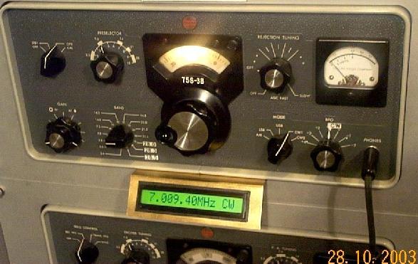
My Collins radios are rack-mounted and, not wanting to drill holes in the aluminum panels, I decided to mount the display externally, as shown below.
For a normal installation, the C75S could be a more convenient choice than the DFD2-S because of the much lower installation work required.
Return to the I0JX home page