Hi, I am Tony I0JX
Why do short antennas not perform
well?
If you are very familiar with antennas, PLEASE do not read this page: firstly, you would not learn very much, secondly you would probably not like the approximations here taken to make concepts easier to understand.
If instead you are not a skilled engineer but, still, you would like to better appreciate the meaning of the common sentence: "short antennas are inefficient", then reading this page could improve your understanding of the matter.
Let us begin saying that a wire antenna starts to become "short" when its length gets lower than one-half wavelength at the operating frequency (one-fourth wavelength for verticals or unipoles). In practice you have to begin worrying when the antenna becomes shorter than half of the above limits. It goes without saying than the same antenna may be "short" at a certain frequency, and "long" at another frequency.
In the following, to simplify calculations, reference is made to a particular frequency, i.e. 1.834 MHz; nevertheless all considerations herein presented are in principle valid for any frequency.
Let us start considering a piece of wire that can be considered to be an extremely short antenna at 1.834 MHz, say 20 cm long, and built with an ideal metal having zero ohmic resistance. Let us call it the elementary dipole. Then, let us assume that some DC current flows through it (for the moment, do not ask yourself how the elementary dipole is fed, this being irrelevant for our purposes). Due to its zero resistance, the elementary dipole will dissipate no power, independently of the amount of DC current (by the Ohm's law, with zero resistance, no voltage can develop across the elementary dipole). So, the DC generator causing current to flow through the elementary dipole does not deliver any power to it.
Imagine now that the DC generator suddenly becomes an RF generator at 1.834 MHz. Then, you can measure that some RF voltage develops across the elementary dipole despite its zero ohmic resistance, this implying that the elementary dipole now absorbs power from the generator. Nevertheless, the elementary dipole temperature will not rise, this meaning that the absorbed power is not getting dissipated. How can all this be explained?
According to the electromagnetic fields theory, a piece of wire subjected to an RF current generates an electromagnetic field whose intensity is bound to the amount of current flowing through it. As an electromagnetic field transports power, that power must come from somewhere: if there are no ohmic losses, power radiated in the space precisely coincides with power taken out of the generator feeding the piece of wire, nothing can get lost.
To model such phenomenon, imagine that any piece of wire contains two resistance components, i.e.:
Clearly, in presence of both ohmic and radiation resistances, power absorbed from the generator will be partly dissipated into heat and partly radiated in the space.
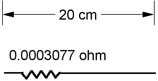
The radiation resistance may be regarded as an invisible resistor embedded in the elementary dipole, the value of which varies with frequency: at DC it is 0 ohm, whilst at 1.834 MHz it is 0.0003077 ohm (according to EZNEC). Picture below represents said model.

As already mentioned, such virtual resistor has nothing to do with the ohmic resistance of the elementary dipole (which we had assumed to be zero), but is just a way to represent the fact that, if RF current causes radiation of power in the form of an electromagnetic field, then the same amount of power must be taken out of the generator causing the RF current to flow (energy cannot be created nor destroyed). While "normal" (i.e. ohmic) resistors transform absorbed power into heat, the radiation resistance transforms absorbed power into a radiated electromagnetic field.
It can easily be shown that the considered elementary dipole is not effective at all in radiating at 1.834 MHz. As a matter of fact, due to its very low radiation resistance, a very high RF current would be needed to radiate a significant amount of power. For instance, for radiating just 100 W @1.834 MHz, an RF current of about 570 A would be needed! This is just the result of the Ohm's law, stating that absorbed power (or radiated power if you will) is:
0.0003077 * (I)2
where I is the r.m.s. RF current imposed by the generator.
Please note that producing 570 A of RF is not an easy task at all, even if the associated power is only 100 W.
Let us now consider a piece of wire 40 cm long, i.e. comprising two elementary dipoles in series. EZNEC now gives a radiation resistance of 0.001248 ohm, which is a bit more than four times that of the single elementary dipole. This means that, for radiating the same RF power, a current about two times lower is now required.
Actually, the radiation resistance increases nearly as the square of the number of elementary dipoles which the considered piece of wire is composed of. If you wish to understand better this, read the Technical Supplement at the bottom of page.
Let us now pass to consider the classical half-wave dipole, which should theoretically be 80 meter long @1.834 MHz. You can visualize the half-wave dipole as consisting of 400 elementary dipoles.

The electromagnetic field radiated by the whole half-wave dipole will be the summation of the individual fields radiated by the 400 elementary dipoles. Then, each elementary dipole shall now generate only a fraction of total field produced by the half-wave dipole, and hence handle a much lower RF current for the same power. RF current, however, will not be the same for all the elementary dipoles, in particular those toward the ends of the wire will carry very little current.
By the above mentioned square law, the total radiation resistance of the half-wave dipole should then be higher than
(400)2 * 0.0003077 = 49.23 ohm
As a matter of fact, EZNEC gives 72.4 ohm for the half-wave dipole.
If 100 W are applied to the half-wave dipole, then the RF current at the feed point will be only 1.175 A.
At this point let us compare the field strengths generated @1.834 MHz by:
One may be surprised to realize that there is not much difference between the two cases! On the other hand, 100 W of RF are effectively radiated in either cases, so what? Play yourself with EZNEC and you will easily get convinced.
More specifically, the elementary dipole and the half-wave dipole have a similar 8-shaped radiation pattern, with just a small difference in gain (some tenths of a dB) along the axis orthogonal to the wire.
At this point the next logical question is: why do people use half-wave dipoles instead of elementary dipoles? To answer the question, we now have to also consider the way dipoles are actually fed.
An half-wave dipole will typically be center-fed by breaking the wire into two 40 m pieces. We having chosen a dipole length (i.e. 80 meters) that is perfectly resonant (@1.834 MHz), the dipole will show a pure resistance of 72.4 ohm, with no reactive component. We can then directly connect the two terminals to a coaxial cable having 75 ohm impedance, with a very good match and power transfer to the antenna.
In the case of the elementary dipole the situation is very different. If we proceed as above, breaking it into two 10 cm pieces, we would realize that, at the feed point, there is a big reactive component in series with the 0.0003077 ohm total resistance. Actually, for the elementary dipole @1.834 MHz, EZNEC gives an impedance of:
Z = 0.0003077 - j 141900 ohm
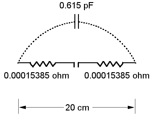
In practice the elementary dipole looks nearly like a small-value capacitor (0.615 pF, showing a reactance of -141900 ohm @1.834 MHz), with a liiiiittle resistive component in series. On the other hand, at @1.834 MHz, the two 10 cm pieces may just be regarded as the armatures of a capacitor.
At 1.834 MHz, the elementary dipole may be electrically modelled with lumped elements, in the following way:

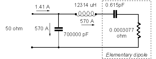
The elementary dipole cannot obviously be directly connected to a coaxial cable due to enormous mismatch which would so result, and a matching network must then be used. Picture below shows an L-C network that would theoretically match the elementary dipole impedance to a standard 50-ohm cable.

To obtain the big 12,314 uH inductance, one could construct a huge coil, e.g. with 460 turns of 3 mm copper wire, wound over a form having a diameter of 30 cm and a length of 1.38 m. The total length of the copper wire would so result to be about 434 meters, with an ohmic resistance of some 1.1 ohm (by the way, this resistance value is so high in our context that the whole L-C network would have to be re-calculated). It is easy to determine that, due to such resistance, only an extremely small fraction of the applied RF power would actually reach the antenna! The matching circuit is extremely inefficient.
In reality, the situation will be even worse than that, due to the copper wire resistance increase caused by skin effect, and to the additional power dissipated in the 700,000 pF capacitor subjected to a huge RF current.
You can adopt other methods to feed the antenna, but whatever approach you take, you will anyway end up with a terrible inefficiency. No way out!
Using antennas much longer than the elementary dipole, say several meters, the situation will improve considerably, however not contradicting the general principle that the shorter the antenna, the higher the losses in the matching circuit.
In conclusion, it can be stated that the poor behaviour of short antennas is mainly bound to the unavoidable losses occurring in the indispensable matching network, and it is not at all due, as many believe, to their presumed "unsuitability" to radiate the electromagnetic field. In other words, short antennas would radiate RF field very well, if one would find a solution to feed them incurring in acceptable losses.
TECHNICAL SUPPLEMENT
Disclaimer: antennas can meaningfully only be treated by mathematical methods. Any attempt to describe things in a less rigorous manner is inevitably destined to fail in some respect. Keep this in mind when reading text below.
First of all an interesting observation. If you compare the radiation pattern of different-length dipoles, you will realize that the pattern of an extremely short dipole does not significantly differ from that of an half-wave dipole, and their gains, as already mentioned, are about equal within a few tenths of a dB. On the contrary, increasing the dipole length beyond half wavelength things begin to change: with 0.75 wavelengths the gain increases by about 1 dB, with 1.125 wavelengths also the radiation pattern gets modified (additional lobes start to appear), with 10 wavelengths the antenna gain goes up by about 3 dB. It looks like there is a kind of threshold effect: until the dipole does not reach some half wavelength, gain remains almost independent of length.
To try and explain such behaviour, let us firstly recall the well known fact that an antenna formed by e.g. two parallel dipoles fed in phase only displays some gain (up to 3 dB) if the two dipoles are distant enough, so that their "capture area" do not significantly overlap each other.
Let us then consider that the half-wave dipole may be regarded as an antenna formed by a great number of elementary dipoles. The reason why, as already mentioned, it does not show a significant gain with respect to the elementary dipole may be attributed to two main concurring effects:
All that said, we can try to explain why the radiation resistance of a 20 cm wire is about four times lower than that of a 40 cm wire (in practice consisting of two 20 cm wire segments).
With a resistance ratio of one to four, for the same RF power the current flowing through the 40 cm wire shall be one half that of the 20 cm wire. This means that the two 20 cm segments of the 40 cm wire will each generate an electromagnetic field halved with respect to the case of the single 20 cm wire. However, at the receive side, the two halved fields will vectorially add up, thus producing the same field (and hence the same power) that would be received when transmitting the same RF power using the single 20 cm wire.
Return to the I0JX home page