By Claudio Pozzi, IK2PII - August 2001
1. Introduction
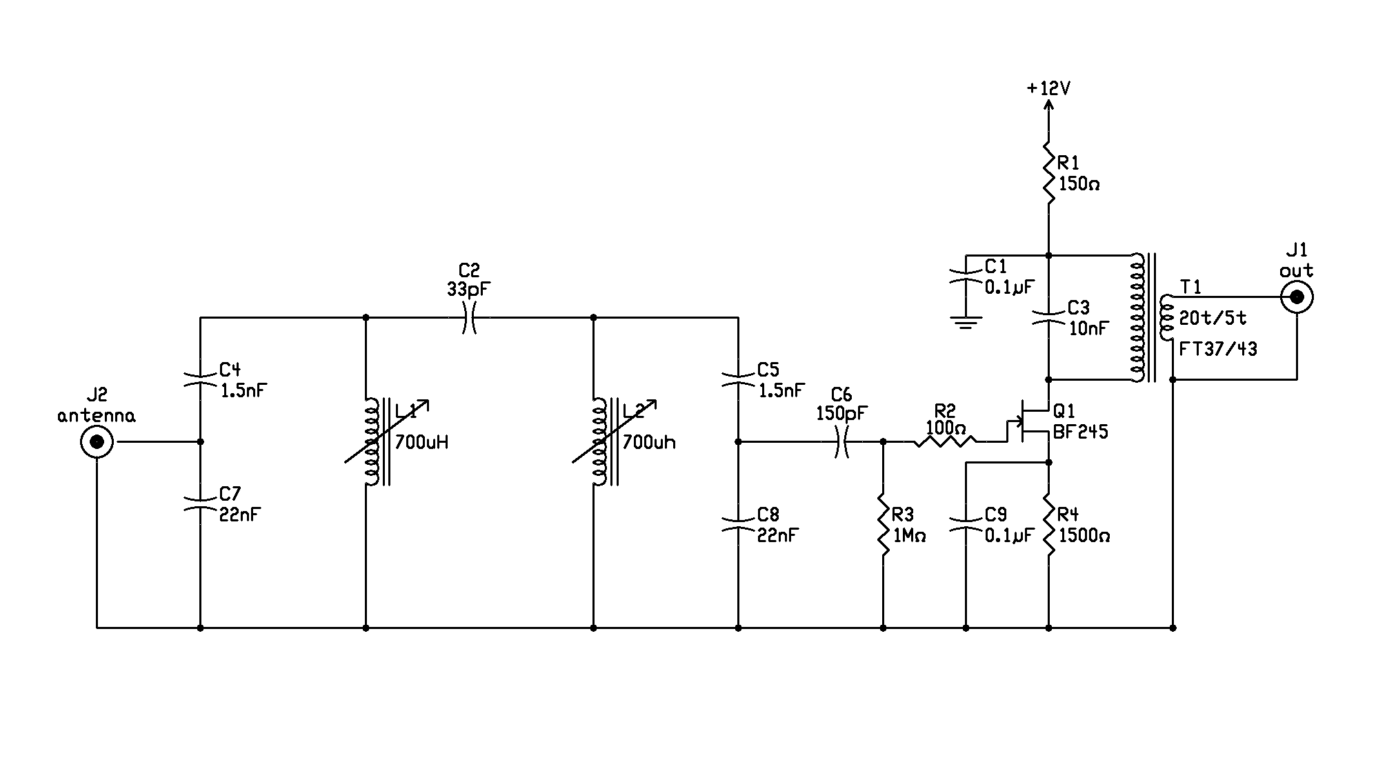
This project was developed to reduce the image
frequency
response of my direct conversion receiver. It can also e useful as
front
end for HAM communications receivers and also for selective level
meters
used as LF receiver. The project focus was selectivity, not gain.
2. Circuit description
The input filter coils are slug tunable 70
microhenry
surplus pot core coils. The capacitor C2 define the filter bandwidth,
was
chosen by trials. Tuning is sharp, centered at 137.650 kHz for the QRSS
portion of the band.
The gain provided by Q1 is enough to compensate the filter loss.
The gain provided by Q1 is enough to compensate the filter loss.
The output transformer T1 is winded on a Amidon
FT37/43 toroidal core; primary is 20 turns, secondary is 5 turns.
