The first stage of the D-104 amplifier provides the load for the mike element. Originally it uses a common NPN bi-polar transistor.
D-104 Discussion
The D-104 has been around since the 30's and is still popular today for communications.
The current ones are still pretty much the same except that in the early 70's a two-transistor pre amp was added to the base.
The D-104 is considered by many to be the coolest looking mike around.
The early elements used a Rochelle salts crystal but later a ceramic crystal was used to make the element more rugged. These elements are unique in that the diaphragm is convex instead of concave. Although these diaphragms were made of aluminum foil, Astatic used an ingenious method of placing batting in contact with the element. This eliminated the "tin" sound of these elements and they are capable of a surprisingly good sound. The peaky sound that we sometimes hear from these mikes is due to improper loading, not the diaphragm material.
Without the pre amp, these microphones sound very good with tube equipment that provided a very high impedance load to the element.
With solid state equipment these elements do not sound as good by themselves. Even with a high impedance load such as 50k ohms, they are often high pitched and peaky sounding. With some applications this high pitched sound is preferred. But sometimes this results in a thin or nasal, unnatural sound. These elements exhibit very low impedance at very high frequencies and very, very high impedance at low frequencies. Even at 50K ohms, output voltage is swamped at low frequencies making the sound high-pitched.
If we bridge the element with a very, very high impedance load, several Meg ohms, it will sound much smoother, be more natural and have low end while still retaining presence.
In the 70's Astatic, made a base available with a two-transistor pre amp. TUG8 followed by the TUG9. It is commonly thought that this was done to make it a CB Power Mike. However the actual reason was to interface the element to modern solid state equipment. This amplifier provided a 1 Meg ohm load on the element and greatly improved the sound with solid state equipment. Even with this pre amp this microphone still did not sound as natural as it did with the element feeding a very high impedance tube grid.
Since that time a device called a Field Effect Transistor (FET) has become popular. One type of FET is the junction FET (JFET). These are frequently used for receiver RF amplifiers and mixers. They can also be used for audio applications and have the advantage of having a very high input impedance of up to 100 Meg ohm. A FET amplifier can be used to bridge the D-104 element at a very high impedance and achieve a remarkably good sound from these attractive classic microphones.
Original Circuit (Amplified
D-104)
The first stage of the D-104 amplifier provides the load for the mike element.
Originally it uses a common NPN bi-polar transistor.
The microphone element is connected through a .01uf capacitor to the base of the first transistor. A 1 Meg resistor is connected from 9v to the base to bias the transistor for linear operation.
The transistor emitter is grounded through a 150-k ohm resistor. A 0.1 uf capacitor also connects to the emitter. This couples the audio output into the next stage providing for DC inter-stage voltage isolation. This is a very common emitter follower configuration.
A 450 pf. (00047) uf capacitor is connected from the emitter to the base. The purpose of this "boot-strapping" capacitor is to create positive feedback from the emitter to the base. This artificially raises the base impedance of this input.
The collector connects to board foil that supplies 9v.
There is a second stage that feeds the mike cord. This is not needed with the FET modification as the FET amplifier provides plenty of output for most applications. I have found that the sound is better without this second stage so it is eliminated in the modification.
Simplified FET Modification
Note! This modification is for use with a D-104 head. If you are using the D-10 dynamic head, leave the pre-amp as is.
It is very easy to replace the first transistor with a JFET greatly increasing the loading impedance across the mike element.
This is a revision of my first modification. It is still simple. I believe that it will provide a better sound than my earlier modification. It uses only one FET and eliminates the second bi-polar stage.
Many JFETS will work. I am describing the use of an MPF-102. It is very common and available at many suppliers such as Radio Shack. It is low noise and good quality.
Remove the battery.
Remove all parts from the original amplifier board EXCEPT the following:
1. 4.7 uf capacitor
2. 33K ohm Resistor (orange, orange, orange)
3. 800 pf ceramic disc capacitor
4. Remove but save the 0.1 uf capacitor for use later at another location.
Remove all wires from the board.
You will need:
1-MPF102 FET
1-220-ohm � watt resistor. (Red, Red, Brown)
1-10 K ohm � watt resistor (Brown, Black, Orange)
1-0.1 uf ceramic disk capacitor saved from original circuit.
Component side of board.
See Figure 2
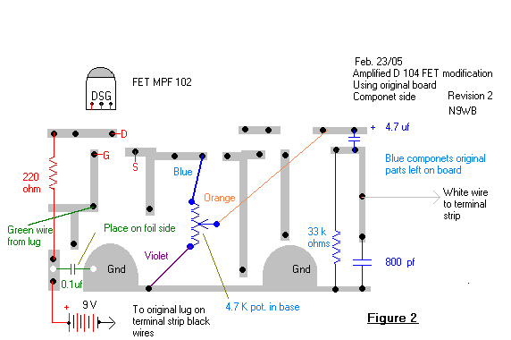
1.
Install the 220-ohm resistor (Red, Red, Brown)on the component side of the board
as shown in the drawing. This is the side without the foil.
2. Install
the FET on the component side as shown in the drawing. With the FET facing you
and the leads going down, the Gate lead is the right one. Be sure that this lead
connects to the foil as shown. This is the foil that looks like a football goal
post with one upper leg missing. The green wire from the terminal strip will
also connect to this foil later.
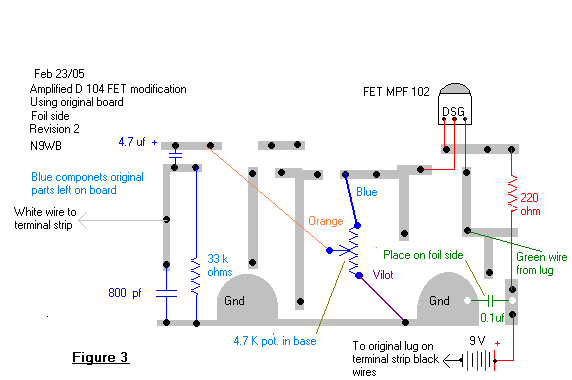
Foil side of board.
(Wires and 0.1 capacitor are connected to the foil side of the board.)
3. Install the 0.1 uf capacitor from the foil that connects to one end
of the 220-ohm resistor to the ground lug foil as shown.
4. Connect the
wires from the 4,700-ohm control as follows. See foil side picture.
Blue wire: Connect this wire to the foil that connects to
the source of the FET as shown.
Violet wire: Connect
this wire to the ground foil on the board.
Orange wire:
Connect this wire to the + side of the 4.7 uf capacitor. This comes from the
center wiper of the control.
5. Connect the Green wire
from the terminal lug to the foil that connects to the Gate transistor lead.
This is the "goalpost foil". This is the output from the mike element.
6. Connect the Red wire from the battery clip to the foil that connects
to the 220-ohm resistor and the 0.1uf capacitor.
7. Connect the Brown
wire from the terminal lugs back to the ground foil on the board. This goes to a
terminal lug that has a yellow wire and a jumper to the ground lug.
8.
Connect the white wire from the terminal lugs to the foil that goes to the 800
pf capacitor, the 33K ohm resistor and the - side of the 4.7 uf capacitor. This
is the output from the board. It goes to a terminal that has another white wire
to it and usually the audio mike cord wire.
*Sometimes this lug goes to
a choke coil or resistor that leads to the mike wire.
I highly recommend
placing a 10K ohm (Brown, Black, Orange) resistor in series with the mike cord
audio lead. Sometimes there is an unused terminal lug available that can be used
for the connection between the resistor and the cord wire. If not, place this
resistor from the lug with the white wires in series to the cord wire and cover
it with tubing or tape.
Install the battery. The black battery clip wire
usually goes to a lug that has another black wire that goes into the neck of the
mike. This is in case it became broken off.
Adjustment:
I have found that this works best with the control in the mike
at about � to � up. With most radios, it should be set for proper level with the
mike gain on the radio at 12 o'clock to 1 o'clock.
Many transceivers
have a pre-amp prior to the mike gain control. This method greatly increases the
signal to noise ratio. However, if this stage is overdriven causing distortion,
reducing the mike gain will not correct this problem. Adjustment as above will
avoid this problem.
RF problems:
The few times
I have seen RF problems with this mike it is usually due to a faulty, cheap
(non-original with poor braid) cord, loose screws holding the pre-amp board or
the head loose.
After you check all this here are some more things to
try.
Place a RF choke in line with the hot mike cord audio lead. This is
the lead surrounded by a shield. Some stands had a small choke there from the
factory. This is in addition to the 10K resistor that I recommend be added.
Place a 47K resistor in series with the green lead leading into the pre
amp board from the mike element. This is the lead that feeds the FET Gate. This
will provide some isolation to the mike head. (undo if it does not help) You can
also try a RF choke here.
If you have replaced your cord and are using
balanced mike cord using one wire for the audio and the other for the switching,
Bypass the switching lead to the shield inside the mike with a .1 ceramic disk
capacitor to the shield ground. A much better solution would be to replace the
cord with a good cord that has only the audio wire within the shield.
If
you experience difficulties contact me on this forum or directly at [email protected].
How this circuit
works.
This circuit uses a Junction FET transistor. This has at least 4
desirable characteristics.
1. Has extremely high gate impedance.
2.
Operates within its linear range with 0 volts gate voltage.
3. Flat
frequency response to many times the audio range.
4. Requires low supply
voltage.
The output from the D-104 ceramic crystal element is fed
directly into the gate of a JFET. This provides a very high impedance load to
the mike element, over 5 Meg ohms, and allows the element to exhibit its natural
audio characteristics. The impedance of the microphone element although very
high provides a resistance sufficient that stray electron buildup does not occur
at the FET gate. This eliminates the need for an additional gate leak resistance
to ground that would increase element loading.
A battery supply of +9
volts is applied to the drain of the FET. The negative side of this battery is
connected by switch contacts to ground. It is only used when the microphone is
in operation.
This + 9-volt supply is bypassed to ground with a 0.1 uf
ceramic disk capacitor and then passes through a 220-ohm resistor to the FET
drain. The resistor provides isolation and provides current limiting for the
FET. It was found that this resistor indeed improved the sound of the
amplifier.
The source is grounded by way of the 4.7 K potentiometer
originally in the mike base.
The wiper of the 4.7 K potentiometer
connects to the + side of a 4.7-uf capacitor. This provides DC isolation and is
a large enough value so as not to reduce low frequency response at the output.
This is a classic source follower circuit and provides a low impedance output
with extremely high impedance input.
An 800 pf ceramic disk capacitor
from the - side of the 4.7-uf capacitor to ground provides RF bypassing. This
value is small enough that it does not reduce high frequency response within the
desired audio range.
A 33 K ohm resistor also connects from the - side
of the 4.7-uf capacitor to ground and establishes a maximum load resistance at
the amplifier output.
I recommend that a 10k resistor be added in series
with the mike cord audio lead as it leaves the microphone.
1. This
further reduces low frequency rolloff through the 4.7 uf capacitor.
2. It
provides RF isolation for the preamp.
3. This limits the minimum load on the
amplifier output.
4. If installed on the mike cord side of the grounding
contacts possible damage to transmitters that provide a voltage for electret
microphone elements will be avoided.
FET Modification to non- amplified
D-104 stands.
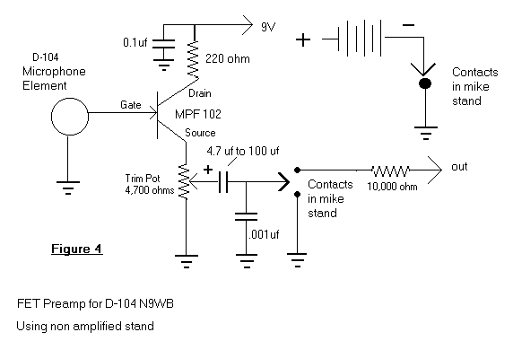
This is a
circuit that is suitable for construction and use in the non-amplified D-104
stand. It is similar to the one used for the amplified stand. Since there is no
original amplifier or board in the non-amplified stand, this circuit will need
to be constructed on a terminal strip or universal circuit board. Since layout
and construction techniques will vary, I have not provided a step by step
instruction. This circuit is simple and requires only basic experience in
circuit fabrication.
As in the other example, I highly recommend a 10k
resistor placed in series with the mike cord audio lead as it leaves the
microphone.
If you experience difficulties or have questions, feel free
to contact me on this forum or directly at [email protected].
Go back
to