GM3WOJ ZL1CT Yagi antenna information
page February 2008
DISCLAIMER - failure to install, maintain or use a
Yagi antenna properly could result in serious injury or death, or damage to property.
You should make SAFETY your prime consideration when implementing any of
the ideas or suggestions given below. I cannot accept any responsibility
for any accident or damage which could be construed to result from any advice
detailed on this web-page.
This web-page describes how to install, adjust and maintain some
common HF Yagi antennas.
1. Origin of the Yagi antenna
The Yagi-Uda antenna was invented in 1926 by Shintaro Uda of
Tohoku Imperial University, Sendai, Japan, in collaboration with Hidetsugu Yagi
of the same University. Yagi published the first English-language reference on
the antenna in a 1928 survey article on short wave research in Japan and it came
to be associated with his name. Yagi always acknowledged Uda's principal
contribution to the design, and the proper name for the antenna is the 'Yagi-Uda'
antenna. Yagi antennas are widely used by amateurs throughout the world on bands
from 160m (!) to microwaves.
2. Development
of the Yagi antenna
There are approximately 10 major manufacturers of HF yagi
antennas currently - the underlying design principles have changed little since its
inception, but computer-optimisation and new methods of feeding/matching the
Yagi to the feedline have improved the electrical performance in recent years.
There have been several books published which cover all aspects of the
mechanical design and construction of Yagi antennas and there are several
software packages available to optimise the mechanical aspects of any Yagi.
Fairly recently, an American company in Washington state is
manufacturing 'SteppIR' Yagi antennas - these have become very popular because
of their ability to cover a number of bands by varying the physical length of
the elements, using metal tape elements unwinding inside fibreglass element
tubes, controlled by stepper motors.
Other multi-band Yagi designs use traps, log cells or
interlaced elements to cover a number of HF bands. In the years before computers
were available to amateurs, many Yagi designs and measurements were subjective.
One popular design which was favoured for many years was the American National
Bureau of Standards = NBS design - this relied entirely on boom length to
achieve increased gain, with the elements being equally spaced along the boom.
UNDER CONSTRUCTION
3. Choosing
a Yagi antenna
It is impossible to give advice about which design or construction
of Yagi antenna would be best for your unique circumstances. It is however
possible to make some general statements about these antennas which might help
you choose. Obviously how much money you wish to invest, if you have a tower,
planning constraints, etc will be major considerations.
14 to 28MHz (20 to 10m) The minimum size of Yagi which really
makes a difference is a 3 element Yagi. A 2-element Yagi might be useful for
occasional portable work, but a 2-ele trap Yagi, for example, may offer no real
advantages over a good wire antenna. Monoband Yagis are superior to all forms of
trap, linear loaded or log-periodic antennas.
7 to 10MHz (40 and 30m) A 2ele Yagi will give reasonable
performance. Here in Europe forward gain is not so much of a consideration, but
front to back ratio (and front/side) is important - a 2ele will give only modest
rejection of signals off the back, but that might be enough to reduce QRM.
3.5MHz (80m) - an 80m Yagi is a very difficult antenna to
construct and keep operational - there are various commercial models available,
but they are *very* expensive, generally flimsy in their mechanical construction
and will over-stress all but the heaviest towers and rotators.
4. Optimising a Yagi antenna
There are a number of powerful antenna modelling and
optimisation software packages which will run on an average home PC. These allow
you to optimise any Yagi design for a variety of parameters - boom length, taper
schedule, forward gain, F/R (F/B ratio), bandwidth, SWR, etc and allow you to
experiment with different types of matching - hairpin, gamma match, etc. They
can iterate the design changes thousands of times per second - it is amazing to
watch the element lengths and position changing rapidly before your eyes,
simulating testing which would take months if done with the physical antenna.
I recommend software developed by Brian Beezley K6STI called 'Yagi
Optimiser' (YO) -although a DOS-based program, this software is easy to use and
gives excellent results.
5. Assembling
a Yagi antenna
Never use element or boom end-caps (except where the element
end-caps are used to retain anti-vibration nylon rope inside the element tips). Boom end caps in particular are a bad idea -
litres of water can become trapped inside the
boom and cause problems.
6. Minimising corrosion of a Yagi antenna
Aluminium is an ideal material for making the boom and
elements of a Yagi - however it is not mechanically strong enough (even when
alloyed) to make the size of nuts, bolts or U-bolts needed on an HF Yagi. These
are usually mild-steel (to be avoided if possible) or stainless steel. Note that
stainless steel bolts and nuts must not be over-tightened, or 'galling' can
occur unless a suitable lubricant or anti-seize compound is used. Galling
is a common problem - stainless steel hardware is prone to galling, as are
tightly-fitting aluminium element sections - if you clean the aluminium surfaces
until bright and don't use 'Penetrox' or similar, it is easy to cold weld the 2
sections together and they may be impossible to separate.
Here is information from WikipediaTM : "Galling
is a cold welding phenomenon which can occur when uncoated stainless steel or
aluminium alloy parts, such as the threads of nuts and bolts, are forced
together. These materials owe their corrosion resistance to the ease with which
they passivate, forming a thin protective oxide layer. The friction scrapes off
this oxide layer from the surface asperities and exposes clean reactive metal.
If the mating parts are of a sufficiently similar material, no additional
activation energy is needed to cold weld them together. Galling
can occur even if the parts are brought together slowly, and it is prevented by
the presence of grease or surface coatings, even if the surface coatings
increase friction. It does not occur when joining dissimilar materials (for
example threading 18-8 stainless into 17-4 stainless) even though both of those
materials are susceptible to galling."
Another common corrosion problem is when a stainless steel (or
mild steel) bolt is inside a closely-fitting aluminium hole - unless a suitable
anti-seize compound is used, the hole fills with a white powder (plus rust if a
mild steel bolt) and can make the bolt very difficult to remove. I *think* this
is galvanic corrosion rather than 'galling'. This website has some interesting
information : http://www.bssa.org.uk/topics.php?article=89 I
am conducting a long-term experiment to determine which material gives the
minimum corrosion when in contact with aluminium - I will report the results
here in due course.
Always use 'Penetrox', 'Noalox', or
similar aluminium-based anti-corrosion paste when joining parts of aluminium
elements which overlap. Always use aluminium rivets when rivetting aluminium
antenna elements (most ordinary pop-rivets are not aluminium but a harder metal
alloy)
Never paint, varnish or use any other coating on the aluminium
elements
of a Yagi antenna - aluminium oxide quickly forms a good protective layer, whilst paint
or varnish can 'creep' into overlapping joints and cause poor
conductivity.
7. Installing a Yagi antenna on the
stub-mast of a tower
The photo below shows a Hy-Gain 205CAS being installed on a
BP80 Versatower.
This method of mounting the
Yagi boom horizontally on the stub-mast first,
then adding the upper half element and the inner part of the lower half element,
works very well, especially for long-boom Yagis. Don't bother with expensive
hinged mast-to-boom clamps, etc - this method is the best - even for complicated
trap Yagis like the useless TH7DXX, beam-in-two-directions-at-once Yagis like
the KT34XA, or riveted antennas like the C3 etc.
You have easy access to all vital bolts, can easily join the
coax to the feed-point, can adjust the tension in any bracing wire or rope, etc. The other parts of the lower half elements are
easily added progressively as the tower is tilted upwards in stages until the
antenna is fully assembled.
8. Connecting the feeder to the antenna
Use a coax loop around the rotator/head-unit - some installations use a 'spiral' of coax
around the outside of the head-unit, sometimes protected inside a length of
hosepipe, which 'winds' or 'unwinds' as the antenna
is rotated - however I have found the simple loop of coax, provided it is not
too long or too short, to be more reliable and less likely to sag and catch on
any bolts, etc. Once secured to the antenna boom at one end and the tower
head-unit at the other, test the loop by moving it by hand in the same way that the
rotator will move it throughout the 360o rotation - does the loop
look as if it might catch on any U-bolt ends or the edges of the mast clamp,
etc. ?
Never apply tiewraps
directly to coax cable - they have sharp edges which will eventually damage the
cable - put a few layers of PVC tape then the tiewrap on top. Use UV-resistant
tiewraps. Seal all coax connectors with self-amalgamating tape (stretched 50%
and overlapped 50%) covered with PVC tape - make sure the taping extends 2"
or so along the cable on each side. Never use self-amalgamating tape on top of
PVC tape. In commercial installations, multiple layers of self-amalgamating tape
then PVC tape are painted with 'Scotchcote' or similar varnish.
Coax and Heliax mounting clips are available, but are usually
not really suitable for use on a tower which can crank up/down - I recommend the type
which have strong plastic rings about 3" i.d. - one at the top of each
telescoping tower section prevents the coax cables + rotator cables from moving about
too much in a gale, but still allows these cables to move freely when you are
raising or lowering the tower.
9. Adjusting a Yagi antenna
Once an HF Yagi is fully assembled on the tower stub-mast
(with the boom still horizontal i.e. parallel to the ground), the tower is tilted towards the vertical far enough for
the rotator to turn the Yagi so that the reflector is parallel to the ground
e.g. about 1 to 2m off the ground. This allows an initial check on the SWR and
resonant frequency to be made - depending on the proximity of other antennas,
etc, these 2 measurements may be close to the final values
obtained with the antenna horizontal at the full height of the tower. Usually
you can still reach the driven element and/or the matching system by using a
step-ladder, so can make initial adjustments to the resonant frequency and the
SWR.
Check these measurements with the antenna at full height -
usually the resonant frequency of the Yagi antenna will move up in frequency
slightly from the tilted-over value. You can lower the antenna and repeat the
setting of the driven element length and/or matching system to achieve the
desired useable bandwidth.
Make a note of the values of resonant frequency and SWR
obtained when the Yagi is newly installed - this gives you a reference set of
values to compare with in future, if you think that some problem has developed.
This is especially important with multi-band Yagis, where a problem can occur on
one band but the other bands may not be affected.
10. Some opinions about current Yagi antennas
I emphasise that these are my personal opinion - I own, have
owned or have used (in contest conditions) all of the antennas on the list below. These comments are based on
my experiences or the experiences of friends whose opinion I trust. Your
experience of the same Yagi may differ from mine. The information below is not
intended to replace wider reviews on e.g. eHam.net
Human nature being what it is, it can be very difficult to concede
that a particular antenna is not actually very good, especially if you have
just spent £1500 to buy it !
My own Yagi antenna experiences :
Western DX33 - 20/15/10 3ele trap
Yagi (obsolete) - my first HF Yagi (in 1980) which
worked surprisingly well - quite strongly constructed, but eventually scrapped when
flying ants kept colonising the traps, resulting in them burning out !
J-beam TB2 - 20/15/10 2ele trap
Yagi (obsolete) - 6' boom - fairly strong, but electrically poor - no gain,
little directivity.
Wilson M415 - 15m 4ele monoband
Yagi (obsolete) - 21' boom - very strong and heavy antenna using a 4" boom.
Old-fashioned 'brute force' design but worked well.
Hy-gain TH3 Junior - 20/15/10
3ele trap Yagi - not very strongly constructed - worked reasonably well for its
size.
Hy-gain TH7dxx - 20/15/10 7ele
trap Yagi - nearly useless - old-fashioned design - unreliable because of too many joints - inside the traps,
steel set-screws are used with aluminium wire (and copper wire in the driven
element traps), hence dis-similar metal
corrosion. Poor front/back ratio. Strongly constructed, so would make good basis
for interlaced monoband beams on the 26' boom.
Mosley Pro57 - 20/17/15/12/10
7ele trap
Yagi - poor on 20m, fair on 15m, reasonable on 10m. I don't want to be too hard
on this antenna because it gave me my best-ever contest results, but it was
lifeless on 20m. Scored lowest (negative gain!) in the 'Champion Radio' survey
of multiband Yagis.
KLM 3ele 40m - linear-loaded Yagi
(obsolete) - worked well but unreliable - too many metal-to-metal joints. High
wind loading. Needs to be at minimum height of 90' above ground to perform
properly. KLM matching system over-complicated - once fixed capacitor system
replaced by better method, matching much easier.
Force 12 C31XR - 20/15/10 14ele
interlaced Yagi - 31' boom - performance on 20m disappointing, better on 15m
and very good on 10m - as you might expect from the number of elements on each
band (3 on 20m, 4 on 15m, 7 on 10m) Perhaps using 3 separate feedlines would
improve performance ?
Force 12 EF-240 - 40m 2ele
linear-loaded Yagi - 18' boom - massive mast clamp adds
considerably to wind loading. Still evaluating this antenna - Force 12 have
changed the design after 10 years of production - now using high-Q traps in
place of the linear-loading wires. ON4UN book indicates a problem of achieving
reasonable F/R because of signal pick-up on the sloping loading wires. My first
observation after installation is that this antenna is affected by nearby
antennas - it needs to be at least 15m away from any other antennas. More
comments a.s.a.p.
Hy-gain 204BA - 20m 4ele monoband
Yagi - 26' boom - good performer - mechanically strong. Could be improved a
lot by computer optimisation and stainless-steel hardware. Early 204BA antennas
used a very poor type of element joining clamp - instead of the usual
jubilee/hose clip it was a custom-made clamp which made a 'dent' when tightened
up - this made the element sections very difficult to separate in the longer
term.
Hy-gain 205CAS - 20m 5ele
monoband Yagi - 34' boom - excellent antenna - well designed, mechanically
strong and good pattern.
SteppIR 4ele - 20 to 6m multiband
Yagi - 32' boom - disappointing - again I don't want to be too negative
about this antenna, but I think there is a fundamental flaw in the innovative
SteppIR design i.e. the minimum SWR, maximum gain and maximum F/R settings do
not coincide - this is a real problem because with a high-power amplifier you
must have the minimum SWR setting. It seems to me that the F/R is mediocre
overall, because of the inability to change the element spacing on the boom. An
expensive antenna, with likely long-term reliability issues. Controller
unreliable.
Creative Design (Create) 10m 5ele monoband Yagi -
21' boom - excellent antenna - lightweight but reasonably strong, good gain,
good pattern. Balun connections are a weak point.
Cushcraft 20-3CD - 20m 3ele
monoband Yagi - 18' boom - works well, but gamma match poorly designed which
results in narrow operating bandwidth.
Cushcraft 40-2CD - 40m 2ele
monoband trap Yagi - 21' boom - very popular antenna - works fairly well, even at 45'
above ground. Uses capacity hats at ends of elements.
Yagi information/comments from friends :
Cushcraft A3S - 20/15/10
3ele trap
Yagi - lightweight, well constructed and good performance for a 3-ele trap Yagi.
Cushcraft A4S - 20/15/10 4ele
(separate 10m reflector) trap
Yagi - works quite well and quite well made.
Cushcraft A3WS - 17/12m 3ele trap
Yagi - works well for size.
Cushcraft X7 - 20/15/10 7ele
trap/mono Yagi - great performer for the boom length
Force 12 XR5 -
20/17/15/12/10 interlaced Yagi - a C3 with WARC bands - works very well.
Hy-gain 155CAS - 15m 5ele monoband
Yagi - excellent antenna - well designed, mechanically strong and good pattern.
Hy-gain 105CAS - 10m 5ele monoband
Yagi - excellent antenna - well designed, mechanically strong and good pattern.
KLM KT34XA - 20/15/10 6ele
linear-loaded Yagi (obsolete - now KT36XA from M2) - 32' boom -
mediocre performance for the boom length - unreliable mechanically - UV
degradation of the insulators (this problem has been addressed in recent
versions I think)
Trident 15m 4ele monoband yagi -
initially there was a manufacturing problem - the boom was wrongly colour-coded,
so antenna would be wrongly assembled and thus perform very poorly. If assembled
correctly, performs well.
TET HB33SP - 20/15/10 3ele trap
Yagi (obsolete) - dual-driven element - poor electrically and very poor
mechanically.
Optibeam
10. Maintaining
a Yagi antenna
UNDER CONSTRUCTION
11. Feeders for Yagi antennas
I have an obsession about feeder losses - why run QRO and have
a good antenna if your feeder is lossy ?
UNDER CONSTRUCTION
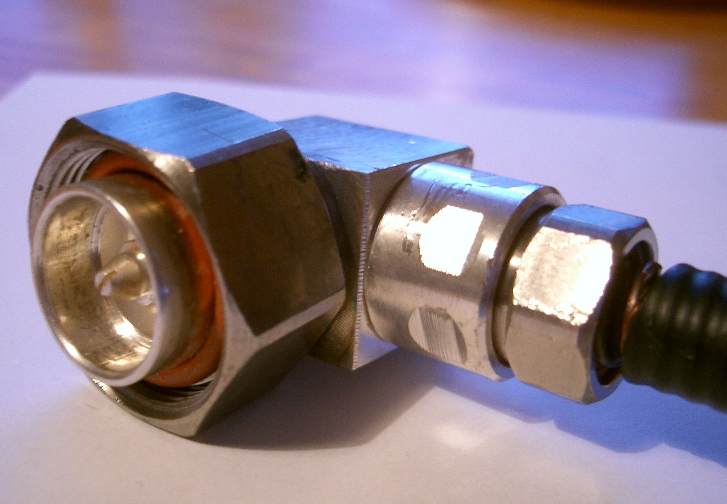
12. Coax connectors
Another obsession I'm afraid - use the minimum number and the
best quality of connectors in your feed system. Remember that we must also
consider the quality of screening provided by the coax feeder. Here is a photo
of one connector which has caused me problems recently. My 20m 5ele Yagi is fed
with Andrew LDF5-50A Heliax until just below the head-unit of the BP80
Versatower, where it terminates in a 7-16 DIN female connector. (7-16 means
inner conductor = 7mm diameter, outer conductor = 16mm diameter)
The
next 25 feet of coax cable is Andrew FSJ4-50B (formerly 'Supaflex') i.e.
flexible Heliax, with a loop around the rotator and along the boom of the
antenna. This Supaflex was originally terminated with an N-type female connector
(cable-mounted socket) which melted - I think it was not the genuine Teflon one
I thought it was.
I replaced the N-type connectors with 7-16 DIN connectors,
fitting a 7-16 female connector to the top end of the 5-50.
This photo shows the (partially dismantled) Andrew F4PDR 7-16
DIN male connector which replaced the frazzled N-type - it is a right-angled
connector which is the only one I had at the time. Right-angled connectors of
any type (N, PL-259, etc) should be avoided - they generally have some
'extra connection' internally to achieve the 90o bend - this leads to
increased unreliability. Some cheap PL-259 right-angle connectors/adaptors have
very thin wire inside - horrible.
This particular F4PDR connector was unreliable because it has
an internal pin + socket - for some reason the inner of the cable and the pin
kept pulling back very slightly and breaking the contact. I took considerable
care fitting this connector and am still unsure why this problem kept
re-occurring - the inner conductor of Heliax cable is glued to the foam
dielectric, so it is difficult for the inner to move separately, which it can do
in e.g. air-spaced coax.
I use a piece of 8mm rope tied to the tower head-unit to take
the (considerable) weight of the LDF5-50A Heliax and ensure that there is no
mechanical strain on the coax joint. At the base of the tower, the outer
insulation of the Heliax is removed and an Andrew earthing strap fitted, which
is bonded to the base-plate of the tower and hence to the main tower earth
system. This prevents RF radiated by the Yagi effectively by-passing the current
balun fitted at the Yagi feedpoint and being picked up on the outer of the
Heliax.
One final point - the inner conductor of FSJ4-50B flexible
Heliax is, when cleaned carefully and lightly tinned, a very good fit into the
inner of an SO-239 socket - this means I was able to fit a PL-259 plug (Teflon)
to the other end of this short length of flexible feeder and plug it directly
into the SO-239 socket on the Hy-gain BN4000 current balun.
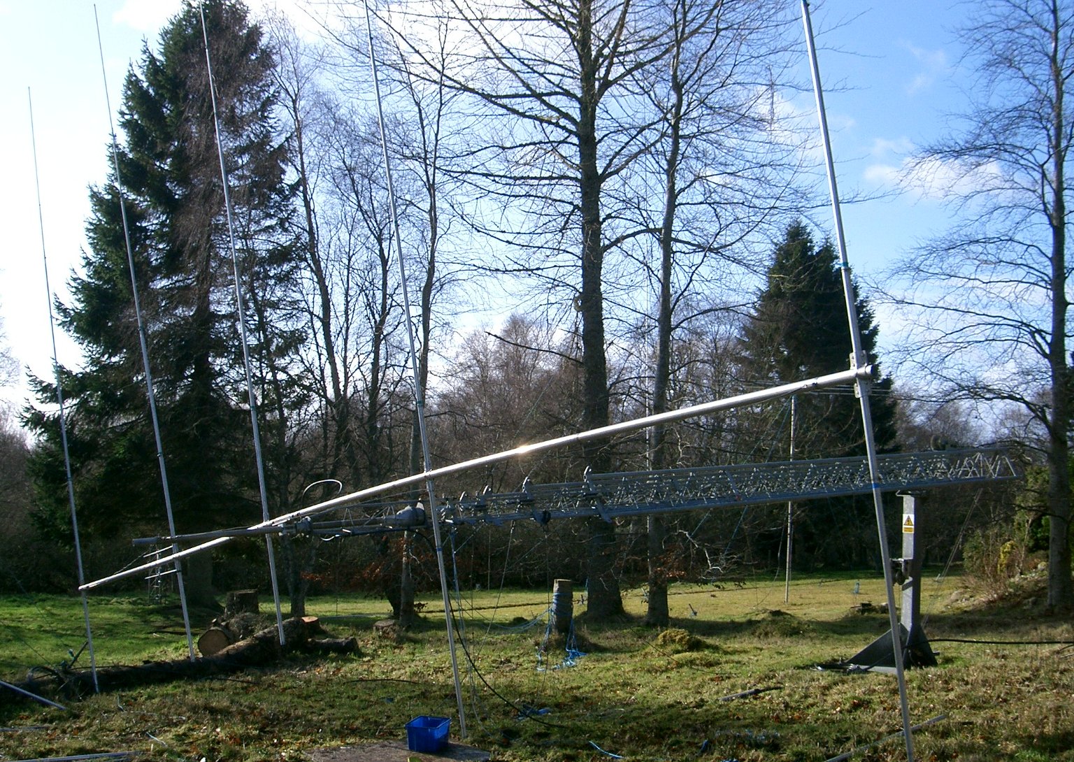
Two Hy-gain 205CAS 20m 5-ele Yagis - at my QTH in 2003 for the GB5HQ 20m CW
station.
26th February 2008 - more info and pictures soon - please
visit later...
 This method of mounting the
Yagi boom horizontally on the stub-mast first,
then adding the upper half element and the inner part of the lower half element,
works very well, especially for long-boom Yagis. Don't bother with expensive
hinged mast-to-boom clamps, etc - this method is the best - even for complicated
trap Yagis like the useless TH7DXX, beam-in-two-directions-at-once Yagis like
the KT34XA, or riveted antennas like the C3 etc.
This method of mounting the
Yagi boom horizontally on the stub-mast first,
then adding the upper half element and the inner part of the lower half element,
works very well, especially for long-boom Yagis. Don't bother with expensive
hinged mast-to-boom clamps, etc - this method is the best - even for complicated
trap Yagis like the useless TH7DXX, beam-in-two-directions-at-once Yagis like
the KT34XA, or riveted antennas like the C3 etc.