Elecraft K3 AGC modification - developed by N6TR March 2012 Chris Tran GM3WOJ / ZL1CT
This webpage describes how to carry out the N6TR AGC modification to the Elecraft K3 transceiver.
DISCLAIMER : This modification is carried out entirely at your own risk and may void any warranty on your radio. Do not attempt to carry out this modification if you are not confident that you can carry it out safely and without causing damage to your radio.
This straightforward modification was carried out on 21st March 2012, by Jim GM0NAI / GM7R, on my K3 serial number 4716 which was purchased new as a kit in September 2010. It is possible that recent factory-built and kit K3s include this modification as standard, but I do not know. We decided to only add one extra 1.0uF capacitor initially, with the option to add a second capacitor later after testing. 73 Chris GM3WOJ
______________________________________________________________________________________________
CLICK ON ANY OF THE THUMBNAIL PHOTOS BELOW TO DOWNLOAD THE FULL-SIZE VERSION ....
1. With the K3 upside down and the front facing away from you, remove the 7 screws which hold the front half of the base covers in place - remove only this front half of the base cover.
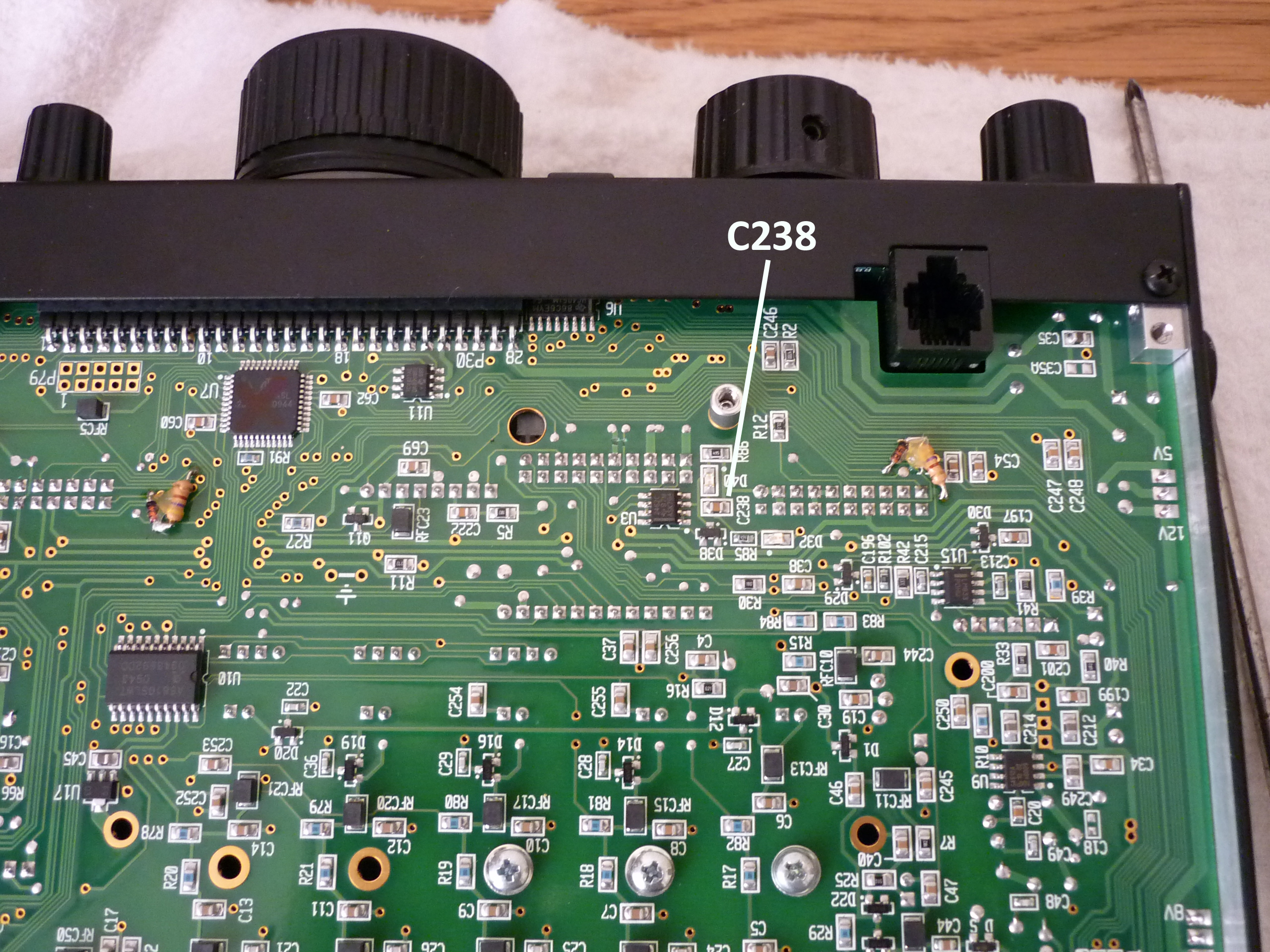
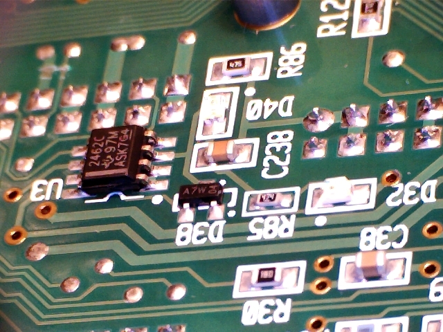
2. Using these 2 pics below to help you, identify surface-mount capacitor C238 (value 0.1uF) The PCB silk-screening is very clear and you should have no difficulty finding the correct capacitor.
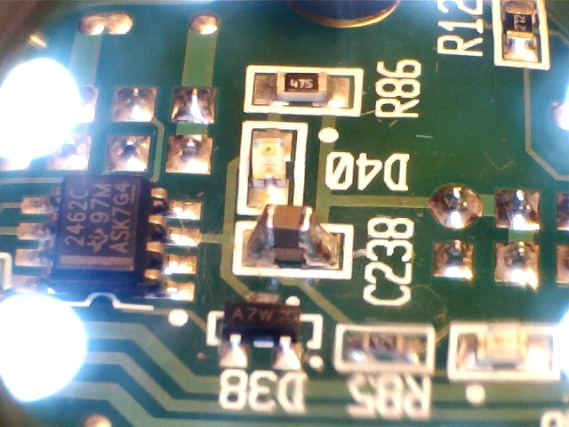
3. Place the new extra surface-mount capacitor (1uF 25V wkg) on top of the existing C238 as per this photo below :
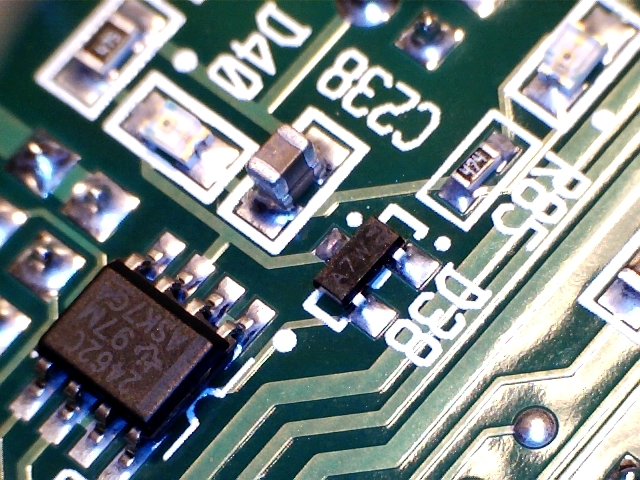
4. Carefully solder both ends of the extra capacitor, so that they are connected in parallel. See photos below :

5. Examine the solder joints - remove any excess flux. Replace the front half of the base cover.
______________________________________________________________________________________________
Here is the original information, as posted on one of the Elecraft reflectors in late 2011 :
Hi all,
The K3's hardware AGC time constant is a compromise between recovery
time and IMD due to modulation of the loop. C238, on the bottom of the
RF board near the front, sets this time constant.
We did a little experiment today (thanks to Tree, N6TR) that suggests
increasing the size of C238 substantially might be a worthy change. In
the case of signals just large enough to tickle the hardware AGC, the
first IMD products were reduced by something like 18 dB. This will
also increase the recovery time for very strong signals, so the jury
is out on whether this is OK for the average user.
For the experimentally inclined: C238 is easy to get to; just remove
bottom cover A (the front half). C238 is a large-ish surface mount
capacitor nestled between two 20-pin connectors. The present value is
0.1 uF. Tree tacked a 1-uF cap on top of it. Then he tacked another
one on, which improved things by another few dB.
Some ops have mentioned problems with signals much lower than this,
which has always baffled me. But I got to thinking: Suppose you're
listening to a bunch of S4-S5 signals in your DSP passband. You could
have larger signals outside the DSP, but inside the crystal filter. Or
you could have clicks from strong signals that get inside the crystal
filter but you can't hear because you're using a narrow DSP filter. Or
you could have noise spikes. Any of these could ping the hardware AGC
just enough to cause IMD between all of the signals in the passband.
My point is that increasing the loop time constant could have a more
general benefit when a band is busy and/or noisy.
Let me know if you try this and whether the results are of interest.
(I live in an RF-free zone, it seems, so I can never recreate the
problem here. Frustrating!)
73,
Wayne
N6KR