
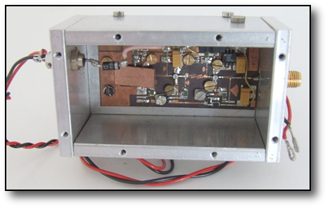
47GHz Equipment
This photo shows the head unit of the 47Ghz DB6NT transverter with, from lower left to right the 11.7 to 23.5GHz LO doubler and the x2 diode multiplier and mixer. The 3-stage LO doubler used NE32584 GaAs fets in an single amplifier configuration followed by a pcb filter, a X2 stage and a final amplifier to produce ~ 50-60mW at 23.5Ghz. The upper pcb is the IF and switching. It was recognised in the first attempt that it was quite tricky to optimise the 23GHz multiplier strip due to the integrated approach. Thus this second version gets round this by having a removable 23Ghz strip which can be optimised into a power meter in its own right. Using this method 60mW was been seen at 23Ghz enhancing the mixing properties of the following mixer diode. A small screw is also visible which allows matching into the diode for best performance. High stability and good phase noise are achieved by using QT crystals in the LO from by Eisch-Kafka in Germany.
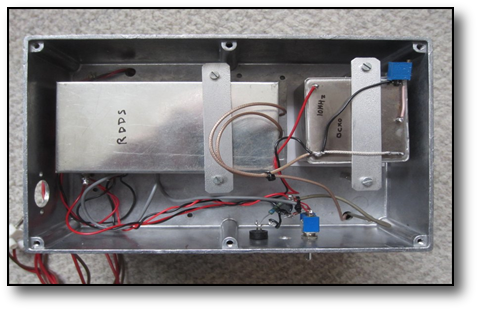
The LO shown below comprised a multiplier chain which provided a signal at 11Ghz mounted in a back to back pair of die-cast boxes. One side contained the crystal oscillator and RF multipliers, the other side shown here, a PLL using the RDDS system, which was locked to a double ovened OCXO 10Mhz source from eBay.

This shot on the right shows the transverter mounted on a waveguide switch and a cassegrain plastic 30cms antenna with the 4mW multiplier source on the Tx port. The LO crystal driver multiplier chain for this 4mW source could be either keyed or audio in the form of FM applied
To increase the chances of a contact a 4mW GaAs FET multiplier, was used and shown here, which comprised GaAs fet multiplier stages using the NE32584 devices, driven by an 11.772Ghz source capable of being FM modulated or keyed for CW.

Why not try a link budget Excel spreadsheet here. This calculates s/n for a given path length knowing the RH and ambient temperature either for an SSB or FM QSO for 24, 47, 76 and 120Ghz and gives some idea if the path will work or not. The Excel workbook comprises 4 sheets. Pick the one for the band your working on and enter the figures where they are shown in blue.
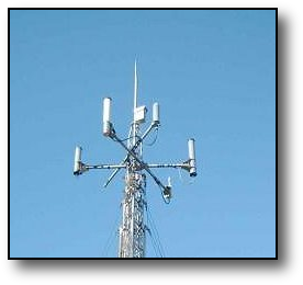
A beacon designed and built by G8ACE was running under my own callsign for control purposes, at the South Coast Beacon site on the south coast. The picture shows the small rectangular box housing the beacon hardware on the mast. However the years took their toll and it went QRT. But recently the mast had to be lowerd so the opportuntity was taken to remove it. It was replaced by the Mk 2 version also by G8ACE, in 2019, with the official call GB3SCQ.
This is currently on it own dedicated mast to allow easy of access and accurate pointing, but which is unfortunately lower than previously. However it still seems to provide a useful signal over the desired area.
Listen to the Mk 1 beacon here over a 42km line of site path in the New Forest.
This is currently on it own dedicated mast to allow easy of access and accurate pointing, but which is unfortunately lower than previously. However it still seems to provide a useful signal over the desired area.
Listen to the Mk 1 beacon here over a 42km line of site path in the New Forest.
47GHz South Coast Beacon
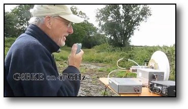
Operation at Batcombe down , Dorset
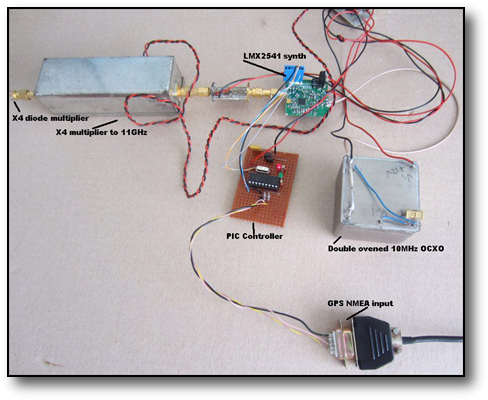
Using the LMX2541 synthesiser chip on 47GHz
Some experiments were made on the bench using the Texas Instruments LMX2541 synthesiser chip. If you purchase the correct version of the device it can provide 3.7GHz signals locked to an external reference which are comparable in performance to a xtal oscillator driving a multiplier chain even up to the 47 & 76GHz. As an LO for a receiver or a stand alone source for an FM transmission these devices seem to be very good with respect to stability and phase noise as long as the reference is good.
I put together a beacon source with JT4G modulation on it as per the G4JNT examples and the resulting signal can be heard here.
The picture at the right shows the lash up used together with the NMEA GPS feed needed to synchronise the timing of the JT4G signal.
I put together a beacon source with JT4G modulation on it as per the G4JNT examples and the resulting signal can be heard here.
The picture at the right shows the lash up used together with the NMEA GPS feed needed to synchronise the timing of the JT4G signal.
For more info on the 47GHz activities across the UK try this link http://www.microwavers.org/47ghz.htm
For a number of years I was active on the 47GHz band and the equipment I used is outlined below. Having got my enjoyment out of it this equipment has now been sold on, for others to enjoy.
And listen here to a typical FM QSO on the band over a LoS 18km path
And if you thought this kit is advanced for its time ...look at this link.