A New Pointer Drive for the HP8555A Plug-in
There are a large number of Hewlett Packard HP8555A 0.01 to 18GHz plug-ins for the HP 141T spectrum analysers around in amateur circles and on the surplus market. One draw back of these units seems to be that the pointer drive mechanism comprising a thin fibre belt can wear with age and eventually snap. This renders the instrument pretty useless and to replace the belt is quite costly.
The following offers a cheaper solution and seems to be just as satisfactory as the original drive.
It comprises replacing the cogged belt drive with a chord and pulley drive. Access to a small lathe is required to turn the new pulley in brass or aluminium.
To get at the drive mechanism one has to proceed with the follow the following steps after the 8555A has been withdrawn from the 141T mainframe and separated from the 8552B IF section:-
Remove the top cover (6 cross-head screws)
Turn the frequency controls to lowest frequency (fully anticlockwise) and ensure that the control is in the "normal" tune position i.e. . (pushed fully in).
Remove the frequency control knobs via the small hex screws.
Next with plug-in front panel facing you unscrew the two countersunk cross-head screws on the left hand side of the unit and nearest the front panel.
Invert the unit and unscrew the two countersunk cross-head screws on the bottom of the unit nearest the front panel.
Looking again on the top of the unit, locate and carefully prise off the D type connector just behind the display. (This has a large loom of wire going to it). The whole front display including front panel should now lift upwards and away from the rest of the unit.
Remove the front panel escutcheon by using an Allen key to undo the "Ext mixer bias" and "Amplitude cal" pots. and also remove the circlip around the frequency control spindle.
This exposes three crosshead screws underneath the "BAND" escutcheon which should be removed.
At the rear of the front panel in amongst the front panel switches are two large nuts. One only has to loosen them off one turn, since the drum assembly is held in position with slotted brackets (clever HP!). The whole tuning drum assembly will then lift clear of the front panel.
Locate the bracket holding the three blue multi-turn pots and remove very carefully by taking out the two crosshead screws holding the bracket to the display. Do not disturb the rotational position of the pots. The long tuning spindle will also come with this assembly together with the "normal / rapid" tuning clutch assembly. This contains 4 sprung ball bearings so be very careful with this!
This will leave on the display section the brass bracket carrying the display drive sprocket and a gear.
Remove this brass bracket by removing the two long cross-head screws and then remove the circlip which holds the sprocket on the hollow shaft. You should now have complete access to the sprocket.
A new pulley can now be turned up in brass or aluminium, with a diameter of 19.2mm, a lip diameter of 20.3 mm and thickness of 10mm. as per the diagram. A hole with diameter of 9.5mm with a small key in it is also required to key it to the keyway in the existing shaft. This can be made by filing a small slot in the pulley and soldering a small piece of brass in the slot . The old sprocket can be used as a pattern. The new pulley must be a good push on the shaft fit otherwise backlash and wobble will occur.
For those unable to get access to a lathe the original sprocket could be modified by carefully filing off the sprocket teeth and sticking two slightly over-sized "cheeks" in thin brass or aluminium to the sprocket, thus effectively changing it to a pulley.
To re-assemble replace the hollow shaft including the new pulley and fasten with the circlip into the brass bracket and screw the bracket back on to the dial assembly.
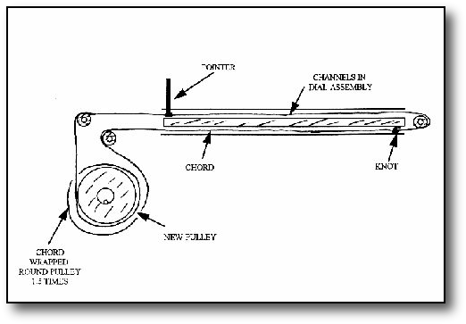
Since the chord used for dial drives seem to be obsolete one now has to improvise! Fishing line of 2-3mm diam can be used or something very similar as long as it will not stretch with time. This is threaded over the path shown in the accompanying diagram and wound round the new pulley 1.5 times. Care should be taken not to loose the 3 small pulleys over which the chord runs. The tricky part is getting the line knotted and in good tension at the same time. Three hands can be useful! Note the knot should run in the lower slot and must not be so large that it prevents the chord running freely. The purist might like to add a small spring at this point to maintain tension, but in practise the loading on the chord is so light that this has not been found necessary. Ensure that the knot is located at the right hand end of the slot as shown and reverse steps 8 to 13 above, taking care again not to move the pot. shafts.
Rescue the aluminium pointer from the old belt by carefully cutting it off, but leaving enough material to fix it to the new chord with a blob of Evo-Stick . A small white mark exists on the tuning dial just above the words above "L.O." and the pointer is located opposite this mark. Ensure again that the tuning shafts are in the fully anticlockwise position i.e. lowest frequency during this process. Before full re-assembly check the free running of the chord from the low to high frequency end of the scale. Reverse steps 1 to 7.
The unit can then be placed in the main frame and checked for frequency calibration against known signals. Providing the tuning pots have not been moved during the process and the pointer has been fixed in the position shown, calibration should be as per the original.
The following offers a cheaper solution and seems to be just as satisfactory as the original drive.
It comprises replacing the cogged belt drive with a chord and pulley drive. Access to a small lathe is required to turn the new pulley in brass or aluminium.
To get at the drive mechanism one has to proceed with the follow the following steps after the 8555A has been withdrawn from the 141T mainframe and separated from the 8552B IF section:-
Remove the top cover (6 cross-head screws)
Turn the frequency controls to lowest frequency (fully anticlockwise) and ensure that the control is in the "normal" tune position i.e. . (pushed fully in).
Remove the frequency control knobs via the small hex screws.
Next with plug-in front panel facing you unscrew the two countersunk cross-head screws on the left hand side of the unit and nearest the front panel.
Invert the unit and unscrew the two countersunk cross-head screws on the bottom of the unit nearest the front panel.
Looking again on the top of the unit, locate and carefully prise off the D type connector just behind the display. (This has a large loom of wire going to it). The whole front display including front panel should now lift upwards and away from the rest of the unit.
Remove the front panel escutcheon by using an Allen key to undo the "Ext mixer bias" and "Amplitude cal" pots. and also remove the circlip around the frequency control spindle.
This exposes three crosshead screws underneath the "BAND" escutcheon which should be removed.
At the rear of the front panel in amongst the front panel switches are two large nuts. One only has to loosen them off one turn, since the drum assembly is held in position with slotted brackets (clever HP!). The whole tuning drum assembly will then lift clear of the front panel.
Locate the bracket holding the three blue multi-turn pots and remove very carefully by taking out the two crosshead screws holding the bracket to the display. Do not disturb the rotational position of the pots. The long tuning spindle will also come with this assembly together with the "normal / rapid" tuning clutch assembly. This contains 4 sprung ball bearings so be very careful with this!
This will leave on the display section the brass bracket carrying the display drive sprocket and a gear.
Remove this brass bracket by removing the two long cross-head screws and then remove the circlip which holds the sprocket on the hollow shaft. You should now have complete access to the sprocket.
A new pulley can now be turned up in brass or aluminium, with a diameter of 19.2mm, a lip diameter of 20.3 mm and thickness of 10mm. as per the diagram. A hole with diameter of 9.5mm with a small key in it is also required to key it to the keyway in the existing shaft. This can be made by filing a small slot in the pulley and soldering a small piece of brass in the slot . The old sprocket can be used as a pattern. The new pulley must be a good push on the shaft fit otherwise backlash and wobble will occur.
For those unable to get access to a lathe the original sprocket could be modified by carefully filing off the sprocket teeth and sticking two slightly over-sized "cheeks" in thin brass or aluminium to the sprocket, thus effectively changing it to a pulley.
To re-assemble replace the hollow shaft including the new pulley and fasten with the circlip into the brass bracket and screw the bracket back on to the dial assembly.
Since the chord used for dial drives seem to be obsolete one now has to improvise! Fishing line of 2-3mm diam can be used or something very similar as long as it will not stretch with time. This is threaded over the path shown in the accompanying diagram and wound round the new pulley 1.5 times. Care should be taken not to loose the 3 small pulleys over which the chord runs. The tricky part is getting the line knotted and in good tension at the same time. Three hands can be useful! Note the knot should run in the lower slot and must not be so large that it prevents the chord running freely. The purist might like to add a small spring at this point to maintain tension, but in practise the loading on the chord is so light that this has not been found necessary. Ensure that the knot is located at the right hand end of the slot as shown and reverse steps 8 to 13 above, taking care again not to move the pot. shafts.
Rescue the aluminium pointer from the old belt by carefully cutting it off, but leaving enough material to fix it to the new chord with a blob of Evo-Stick . A small white mark exists on the tuning dial just above the words above "L.O." and the pointer is located opposite this mark. Ensure again that the tuning shafts are in the fully anticlockwise position i.e. lowest frequency during this process. Before full re-assembly check the free running of the chord from the low to high frequency end of the scale. Reverse steps 1 to 7.
The unit can then be placed in the main frame and checked for frequency calibration against known signals. Providing the tuning pots have not been moved during the process and the pointer has been fixed in the position shown, calibration should be as per the original.
A useful source of spare parts for older HP units is Sphere Research Corporation