Following on from my experiments a few years ago with renovated G8LMW transverters reported here, I wanted to have another play on this band, but with some more modern equipment.
And as I'd had my Notice of Variation to use the new allocation of 2300-2302MHz for 18 months and done nothing about it, I was keen to make something which would work just as easily at 2300 as 2320MHz.
Now I still had my modified Panorama MMDS downconverter working very well on receive, so I really only needed a transmitter to get me started. And thinking of something which could produce a clean output without any narrow RF filtering (which would then compromise its ability to work at 2300 & 2320), I deciced that direct conversion would be a good approach.
If I could generate a Local Oscillator directly at the required RF frequency, and modulate this by the phasing method, I could produce an SSB signal relatively easily.
Considering my LO, I already had an RFExplorer Signal Generator, but I'd also seen a lower-cost version with just a USB control.
But what of the upconverter and RF amplifiers? I had a look at the Farnell website to see what low-cost components were available.
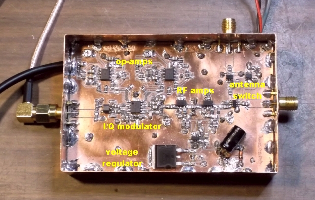
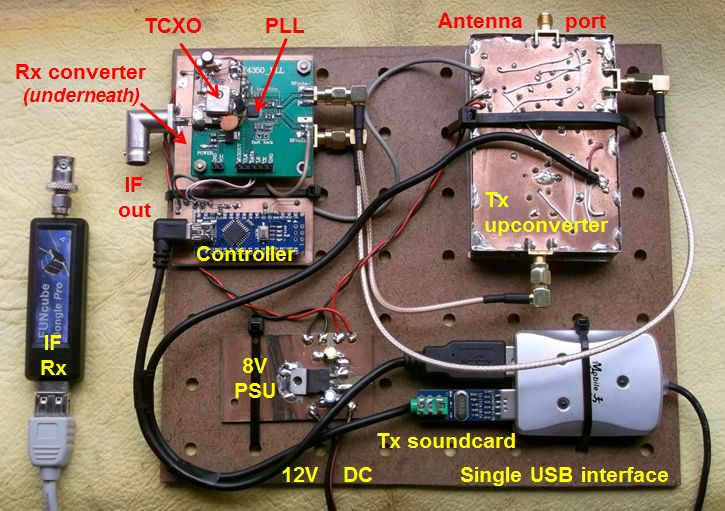
There were lots of tiny QFN devices, but I really wanted larger SMDs with legs, which I'd have a chance of hand-soldering at the first attempt! So I settled on the AD8349 from Analog Devices: this is specified up to 2700MHz and is in a 16-pin SOIC package (but with 0.65mm spaced pins!). I also chose a couple of AD RF amplifier stages to take my Tx output up to 0.25W, and an antenna-switch IC so that I could share the antenna with my MMDS downconverter (unlike my previous systems which used separate Tx & Rx antennas).
I designed my circuit-board using the free DesignSpark software, and had it made by a friend who has a CNC milling machine: this couldn't quite manage all the fine tracks to the AD8349, so I had to touch these up using a scalpel under a microscope! But I did manage to populate the board by hand (using the microscope again, and a very fine-tipped soldering iron), including connecting the ground-pad under the AD8349 (I made a small square slot in the board, and formed my own "plated-through hole" using a couple of strips of copper-foil tape).
So now I had an LO and upconverter, but how to obtain the quadrature components of my modulation? I'd already identified the G3PLX IQ transmitter program as a suitable source, and planned to fit a mini USB-sound card close to my upconverter to feed the modulation into my I & Q inputs. This worked better than I'd dared hope, and I had my 250mW SSB signal ready just in time for the July 2016 UKAC.
Now I'd had some past experience of using a separate Tx & Rx on 13cm, when I used the twin tuning-dials of my IC202 and FT817 for frequency-netting. But this time I had an even more tricky problem: my Tx LO could only move in 1kHz steps, after which I had to enter (by typing) the offset frequency in Hz into the G3PLX program! This took some getting used to, but after a little practice I was ready to try it out on-air.
Dave G4JLG was operating portable from Winter Hill that night, and I could hear him very strongly calling "CQ", so I went through my manual netting procedure and gave him a call back. I felt both triumph and relief when he replied straight away with a very complimentary signal report - in that instant all my hard work had been worthwhile!
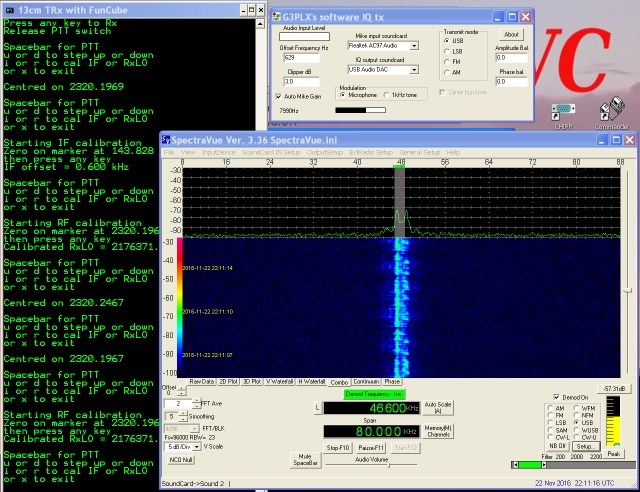
Over the following weeks I worked on improvements ready for the August UKAC. First I made a USB "CAT" interface lead for my FT817 and wrote some Python code to read its dial-frequency. I then incorporated this into my program for controlling the USB-LO, and added a semi-automatic calibration routine to help track out the differential drift between my Tx & Rx oscillators. This program also calculated the offset frequency which I needed to type into the G3PLX software, but then I had a breakthrough, thanks to PyWinAuto: using this code, I had the program paste the offset frequency automatically into the Edit-box, so my frequency-netting process is now just a single key-press!
As it was a dry evening, I managed to rig up my prototype on the mast, linked only with DC power, USB (for LO control & modulation), a PTT-line and Rx IF (at 143MHz). Using this lash-up, I had two QSOs, including Mark M0UFC/P at a distance of 36km from my home QTH.
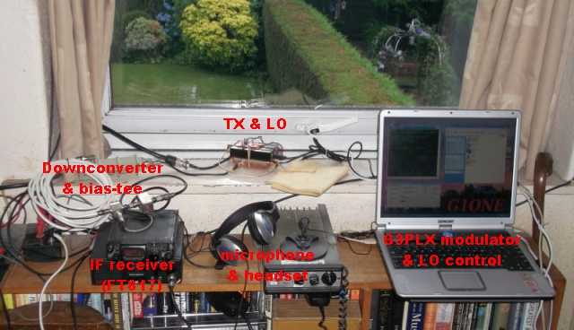
Next I looked at using an SDR-dongle on receive instead of my FT817. I found a way to link this into my Python program (using SDRSharp and its Net Remote plugin), but my old freecyled WindowsXP "scraptop" computer wasn't powerful enough to run all the programs properly in real-time. Then I discovered that the SpectraVue program was a lot less CPU-intensive than SDRSharp, and I could link via its SVExtControl interface to my Python code, so now I have a complete SDR transceiver solution, using an old FunCube Dongle on receive. My program even mutes the Rx audio when I go over to Tx, so I don't need to keep taking my headphones off! I successfully tested this in a QSO with Dave G4JLG/P during the November 2016 UKAC session.
Then in the autumn of 2019 I built my own receive downconverter to take the place of the Panorama unit. This uses a low-cost ADF4350 development board (locked to a TCXO) to provide the LO for both Rx and Tx sections. This requires SPI control, which I've provided from a little Arduino Nano board, driven via USB from my Python code.
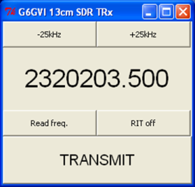
When I expanded my Python programming skills to include the Tkinter Graphical User Interface package, I could dispense with the rather unwieldy text-console scrolling down the screen and have a compact GUI with push-button controls and updating display windows. I've included tuning buttons for stepping up and down the band (as the continuous bandwidth of my FunCube receiver is only around 80kHz).
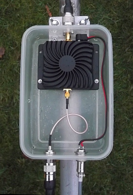
The next step was to transplant all this hardware into a diecast box which I can mount at the masthead just beneath the antenna. From there I only need cables for DC power, USB and IF output coming down to the shack. I tested it on air across town with Steve G4AQB at the start of October 2019.
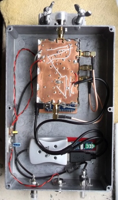
Then a few weeks later I acquired one of the "WiFi booster" amplifiers which some stations have used on their OSCAR 100 uplinks. I found that it had around 13dB gain on transmit but more like 25dB on receive, so I bypassed the second Rx stage to make it more symmetrical. I put it in a plastic box for masthead mounting, so now I can leave my SDR unit on the windowsill and just have the PA/LNA up in the air. Driving it from my SDR unit, I'm getting up to 2W output straight into the antenna.
I first tested this on air during the November 2019 13cm UKAC and then used it through all the 2020 sessions: my average score was 73% up on the previous year (when I'd used a transverter with similar output power), so the waterfall display certainly helped me to catch more signals.
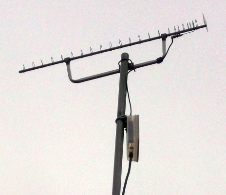
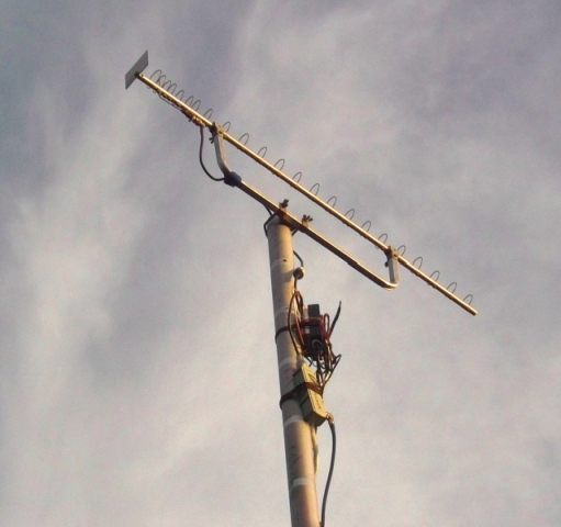
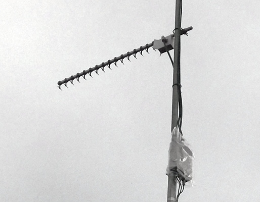
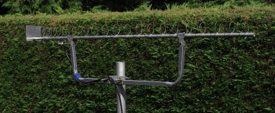
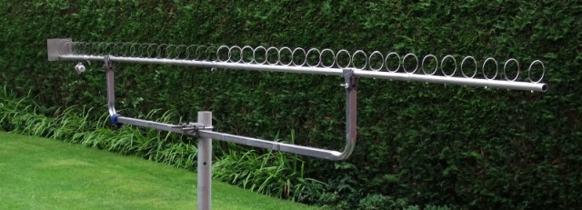
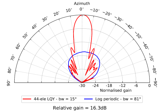
After using this through the first half of the 2020 UKACs, I decided that it would be worthwhile increasing my antenna gain. So I managed to cobble together an extension for my loop-quad, upgrading it from 24 to 44 elements and doubling its boom-length. The extra gain did help to work a couple of the weaker signals, but the narrower beamwidth made it more tricky to peak up.
This larger antenna helped me to make another 36% improvement in my average UKAC scores in 2021, compared with 2020.
In 2022 I measured its radiation pattern and assuming a gain of ~5dBi from the Reference (PCB) log-periodic, I have achieved a gain in the order of 21dBi.
My UKAC results in 2022 were very similar to the previous year, and in addition to more contacts with G8CUL & G7LRQ, I also managed to reach John G4ZTR at ~290km on a few occasions - this far surpassed what I'd ever hoped to achieve with my cobbled-together QRP station!
If you'd like more information on this project, then please get in touch.