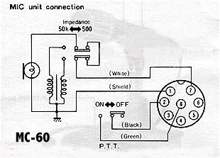
PLEASE NOTE !
RF Feedback has been experienced due to a connection error in
the above schematic. The correct connections are below.
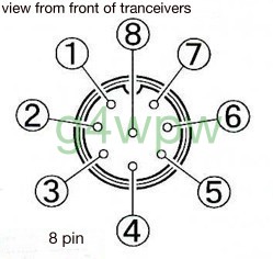
PIN 1 MIC.(white)
PIN 3 DOWN.(blue)
PIN 2 PTT.(black)
PIN 4 UP.(red)
PIN 5 N/C.
PIN 6 N/C.
PIN 7 MIC GROUND (shield/braid)
PIN 8 PTT GROUND (green)