FERITE BALUN 1.8 - 30Mhz
diagrams and photo's g4wpw


THE COMPLETED BALUN.
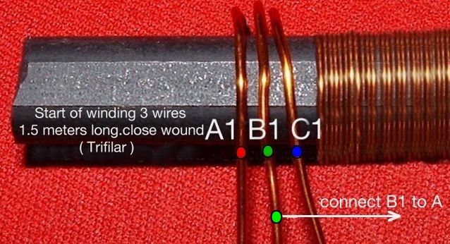
The balun is constructed using a 2.5 inch x 0.5 inch ferite rod,"Ferite rod's" can
be cut to size by making a slight cut around the rod with a sharp hack saw,then
grip the rod very tightly and give it a good tap down on to a bench, just above
the saw cut ,it should break at or near the cut point.
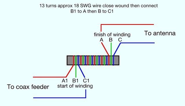
When the "BALUN" construction is complete a 50 ohm carbon resistor
connected between points A - C should give swr of 1:5 -1 or less
Although Ferite baluns do a good job,at high power ,100W or more the ferite core
may saturate causing harmonics to be generated,this can cause TVI
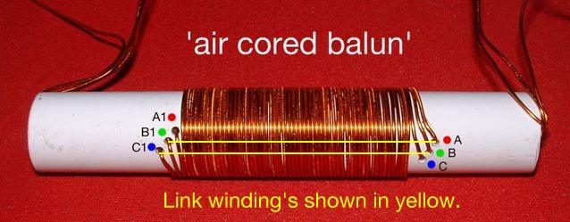
The construction is exactly the same for higher powered "air cored balun"
but with 1 inch diam former, approx 4 inch long, using 16 swg enamel wire
This balun will handle 3kw without any problems
The finished balun's should be encased or insulated from the elements.
4:1 BALUN.

The construction for this balun uses the same principles as the previous one
use a 300 ohm carbon resistor to check the swr,this should again be 1:5 - 1 or less.
The balun can also be constructed using a T200-2 or simular Toroidal iron core
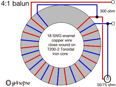
a small gap must be left between the start and finish of the windings
BALUNS.
balanced ( bal ) to unbalanced ( un ) hence "balun"
When a balanced antenna such as a dipole or a beam is fed with an unbalanced
( coax ) feeder,RF currents can flow down the feeder causing radiation to occur
from the outer braid,although these RF currents are cancelled in twin feeder by
the oposite electromagnetic field ,in unbalanced feeder ( coax ) this cannot occur
because the center core of the feeder is effectivley trapped by the outer braid
cylinder the result could cause RF FEEDBACK IN THE SHACK ,TVI PROBLEMS,CHANGES
IN THE ANTENNA RADIATION PATTERN.
This is where the Balun comes in
Baluns are not solely dependant on the number of turns,more on the fact that the
turns are wound close together so that the electromagnetic field in one turn is
also present in the next turn and so on, As the windings are connected in the
opposite phase,the cancelling effect caused by this prevents any RF currents flowing
down the coaxial feeder.
As seen on the 4:1 diagram a balun can also be used as an impedance matching device.