


|
Page last updated: 04/10/2012 |
OZL coils
General description:
Once upon a time we were able to easily obtain RF coils and transformers suitable for tuned circuits in home brew radio equipment, good for any project from VLF through to UHF. Alas the mass production manufacturers have long since stopped producing such components. The likes of Denco and Repanco both of who manufactured quality RF coils and transformers when I first became interested in radio, and latterly Toko no longer produce components suitable for the DIY radio enthusiast. From time to time small production runs can be found, but there availability seems to be somewhat sporadic at best.
During my extensive searches for RF coils and transformers however, I came across the web site of (JF1OZL) Kazuhiro Sunamura. He has provided excellent details of home brew equivalent to some of the Toko coils once available to DIY radio constructor. His original details can be found here http://www.intio.or.jp/jf10zl/ozlcoil.htm don't forget to look over the rest of his site as there are many superb projects and idea's to be found there too http://www.intio.or.jp/jf10zl
Below you will find my interpretation of the details found on Kazuhiro's site...
Donor coil types:
Our first requirement is an appropriate coil former, Kazuhiro suggests we might find suitable donor formers in old fm radio receivers. Here we find two generic types, I have included pictures below to assist with identification:
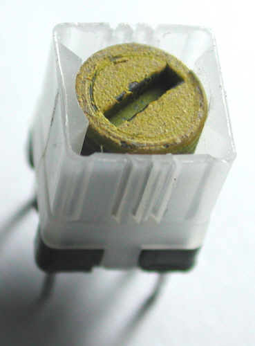
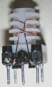
Type A formers, typically used as IF transformers and may be rewound for operation on the lower HF amateur bands
L427 L411
The pictures above represent type A formers, note that the L411 has a ferrite core not pictured which encloses the windings in much the same way as the L427.
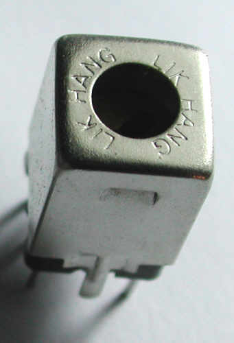
Type B formers, typically used in the RF front end stages of FM receivers, CB radio's etc, and may be rewound for operation on the upper HF amateur bands


425 (Toko)
These pictures represent type B formers,
Rewinding donor coils:
Once the donor coils have been harvested and a suitable one identified, the original windings need to be removed and the pins cleaned and re tinned. Next rewind the coils using the table below as a guide as to the number of turns required. OZL dash coils have a greater Q and as such tuned circuit bandwidths are narrower than the standard OZL coils, whilst OZL dash II coils have a center tapped link winding
As to wire gauge, I use between 28swg and 38swg wire the heavier gauge wire for coils with fewer turns. Hand winding coils with wire gauges much finer than 38swg can be difficult, breaking the wire being the main issue. I choose a wire gauge such that the coil is filled with the windings.
The L411 donors can be a little more fiddly to handle than L427 donors, particularly when using very fine wire gauges.
You may find it necessary to add or subtract a turn, depending upon the specific donor found.
| Band | Frequency | Coil type | OZL, OZL_dash, & OZL_dash_II Tuned winding |
OZL Link winding |
OZL_dash Link winding |
OZL_dash_II Link windings |
Tuned winding inductance | Required padding capacitor | ||
| a/b turns | b/c turns | d/f turns | d/f turns | d/e turns | e/f turns | |||||
| 160m | 1.8 - 2.0MHz | A | 17 | 17 | 12 | 5 | 5 | 5 | 18uH | 390pF |
| 80m | 3.5 - 3.8MHz | A | 10 | 10 | 7 | 3 | 3 | 3 | 9.4uH | 220pF |
| 60m | 5.0 - 5.2MHz | A | 9 | 9 | 6 | 3 | 3 | 3 | 6.75uH | 150pF |
| 40m | 7.0 - 7.2MHz | A | 7 | 7 | 5 | 2 | 2 | 2 | 4.31uH | 120pF |
| 30m | 10.0 - 10.2Mhz | A | 6 | 6 | 4 | 2 | 2 | 2 | 3.13uH | 82pF |
| 20m | 14.0 - 14.5MHz | B | 6 | 6 | 4 | 2 | 2 | 2 | 1.85uH | 68pF |
| 17m | 18.0 - 18.5MHz | B | 6 | 6 | 4 | 2 | 2 | 2 | 1.65uH | 47pF |
| 15m | 21.0 - 21.5MHz | B | 5 | 5 | 3 | 1 | 1 | 1 | 1.44uH | 39pF |
| 12m | 24.5 - 25.0MHz | B | 5 | 5 | 3 | 1 | 1 | 1 | 1.24uH | 33pF |
| 10m | 28.0 - 30.0MHz | B | 4 | 4 | 3 | 1 | 1 | 1 | 1.08uH | 27pF |
| 6m | 50.0 - 52.0MHz | B | 3 | 3 | 2 | 1 | 1 | 1 | 0.68uH | 15pF |
| 4m | 70.0 - 72.0MHz | B | 3 | 3 | 2 | 1 | 1 | 1 | 0.43uH | 12pF |
| 2m | 144.0 - 146.0 MHz | B | 2 | 2 | 1 | 1 | 1 | 1 | 0.17uH | 6.8pF |