BALANCED ANTENNA MATCHING UNIT
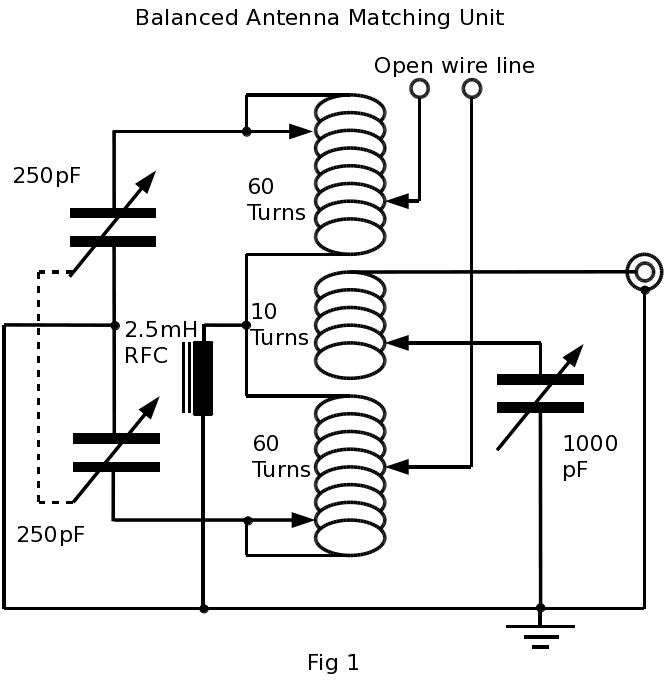
Figure 1 shows the circuit of the matching unit. This comprises of two coils of 60 turns with a link of 10 turns in the middle. The two 60 turn coils are tuned by a twin gang wide spaced capacitor. The link winding is tuned by a twin gang 500pf airspace tuning capacitor with the two stators wired in parallel.
The coil tappings are achieved by mounting a series of 4mm sockets on a perspex strip. By using stackable type 4mm plugs the full range of matching can be found easily.
COIL CONSTRUCTION
Figure 2 shows the construction of the coils.
For ease of construction I suggest the coil is constructed in three sections, the two main 60 turn coils and the 10 turn link coil.
You will need 4 wooden quadrants about 9 inches long and a fillet about quarter of an inch thick and slightly longer than the quadrants, this to make removing of the wood parts easier when the coil is completed.
The quadrants, fillets and the perspex are bound together firmly. Using a vice and a high wattage soldering iron the wire can be melted into the perspex, turning the assembly in the vice every half-a-turn or so.
When the coil is completed the fillets can be removed by pulling them out of the assembly, this will free the quadrants.
The gauge of wire should be as thick as you can manage, the best wire to work with I have found is 2.5mm twin and earth mains cable with the insulation stripped off. As there is no tinning on this wire, the heat transfer is much greater than on the usual tinned type.
The completed coils can then be mounted end-to-end, with the ten turn link coil in the centre of the two 60 turn coils, which makes one long coil.
A word of warning, if you are mounting the coil on pillars use nylon screws in the vicinity of the coil, as steel ones will heat up! due to the magnetic effect of the coil, as I found out to my cost when smoke issued from the perspex the first time I tried the A.M.U.
This is a picture of the front of the AMU:
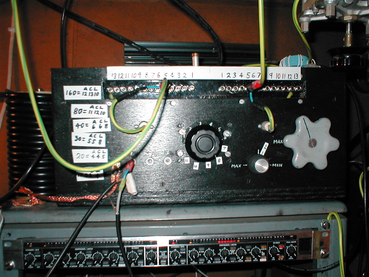
The 4mm sockets to connect the antenna and the capacitor can be seen along the top of the AMU, the centre knob is the link switch, the grey knob is to tune the main capacitor, the link tuning capacitor knob can be seen between the two. The unit in the rack below is the Behringer compressor and noise gate.
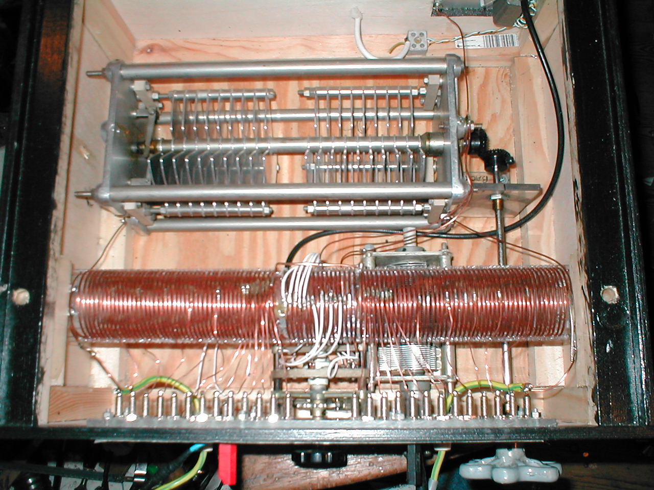
Again the 4mm sockets can be seen, I used a strip of Lexon® to mount the sockets on because its more durable than Perspex which can split if its not drilled carefully.