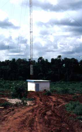
The Coil House and Mast at the Master Station at Ikorodu.

View of the Mast side of the Coil House showing the Base Insulator. (Station looks like the Purple Slave at Abeokuta).
When this photo was taken, the antenna coils system had not yet been installed, and a wire can just be seen to the right of the base insulator to ground the mast. If the mast were not grounded, a high potential static charge would build up on the antenna in a matter of seconds - as I once discovered. You never made that mistake twice.
Normally the mast would be grounded via the centre coil of the antenna tuning system.
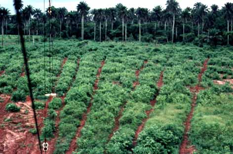
View of part of the Radial System. About 35 radials each 150 metres long were used for the counterpoise of each antenna. The radials were bare stranded copper wire of about 6 to 8 sq. mm cross sectional area and were laid in trenches about 150mm (6") deep.
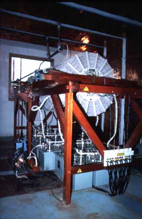
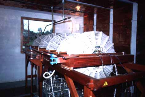
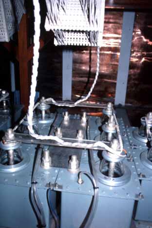
The main "bandspread" coils in their full glory. The coil system was truly both a work of art and an example of excellence in RF Engineering.
The term bandspread has a different meaning in Decca terminology than as used by Amateurs. The antenna system did produce 5 distinct resonances for the 5 different frequencies which each station radiated.
However a common mistake was to assume that there were five coils because the station transmitted on five frequencies. In fact the interaction between the five coils due to mutual inductance and capacitance turned the antenna coil system into a very complex network - the electrical equivalent in VHF/UHF systems engineering would be a transmitter combiner using both cavity filters and isolators.
The outer four basket-weave coils were tuned by large oil-filled mica capacitors on the floor below the coil. Each capacitor was 500pF and the number of capacitors per coil depended upon the required resonance.
The centre coil was physically connected between the antenna and ground, and performed two critical functions - to tune the antenna, and provide coupling between the antenna and the other four coils.
A single coil-capacitor combination as an isolated entity did not resonate near the desired frequency. In very simple terms, the whole antenna tuning and coupling network could be likened to a set of over-coupled tuned circuits. Four of the circuits were tuned by standard capacitors, the fifth being tuned by the capacitance of the antenna. As with conventional over-coupled tuned circuits, resonance peaks occur elsewhere than the designed frequency, and this was the basic concept of the Decca tuning network.
With conventional over-coupled tuned circuits, tuning of the resonance peak can be effected by moving the coils relative to each other, and this was part of the procedures used when commissioning the coil system on a Decca Station.
The output of each transmitter would be fed to the coil system via a motor driven "T" matching network. Each transmitter would be fed to all of the coils via a sets of coupling loops, one per transmitter per coil, the coupling loops for a given transmitter being all connected in series. Depending upon the number of turns on the coupling loop, its phasing polarity to the coil, and to the other transmitter coupling loops, each transmitter could be effectively coupled to the antenna, and at the same time, a high degree of isolation could be obtained between all transmitters.
However unlike the cavity type of transmitter combiner as used in VHF/UHF systems, the electrical characteristics of the Decca antenna, being an electrically short radiator, varied considerably with changing weather conditions, and the coils were mechanically tuned to compensate for these changes. This tuning action comprised of rotating a variometer located in the centre coil and moving a carriage holding two of the coils.
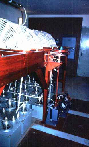
A better view of the moving trestle. Note the copper Faraday screens encircling the inside walls, floor and ceiling of the building.
A total of four such screens were used for each coil house and were simply copper foil, about 1 metre wide and 0.5 metre apart, fixed to the floor, walls and ceiling. These Faraday Loops were to provide an electrically stable environment for the antenna tuning network isolated from external influences such as rain etc.
These coils were bonded to a ring of copper approx 35mm wide by 6mm thick fixed around the outside of the building walls. The counterpoise radials were brazed to this ring."
As mentioned above, part of the commissioning procedures for the coil system involved physically moving the coils relative to one another. The coils simply rested on the trestle on round spindles, and the tuning handles as used during commissioning can be seen resting on the moving carriage nearest to the camera just to the left of the blue push rod bearing.
Due to the intense induction fields around the coil system, the use of metallic components was avoided where possible, and if used had to be grounded. Brass was the mandatory material for screws and other fixings, as apparently some time ago, probably in the early years of the company, a coil house had burnt down, the cause of the fire was attributed to using steel woodscrews.
A view of the tuning mechanism. The meters on the floor are measuring aerial current.
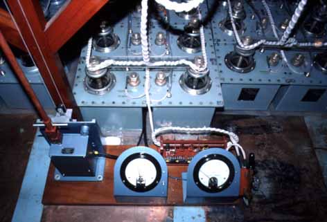
The tuning motor (left) and the aerial current ammeters. The left one works from the current transformer assembly to the rear. The ammeter on the right is a RF thermocouple ammeter, but is normally shorted out with the knife switch to the right to minimise damage due to a lightning strike.
The current transformer assembly actually consisted of four current transformers on a common tufnol tube. Each current transformer was simple a few turns of insulated wire on a ferrite ring. The "earthy" end of the centre coil was connected to the RF thermocouple ammeter, passed through the tufnol tube twice and then grounded to one of the copper Faraday Screens. One of the current transformers was for the moving coil ammeter, and the other three current transformers were used to sample the transmitted signal for the three phase control bays in the main building.
The left moving coil/current transformer RF ammeter had an impressive FSD of 50A, and the right Thermocouple meter had an FSD of 30A.
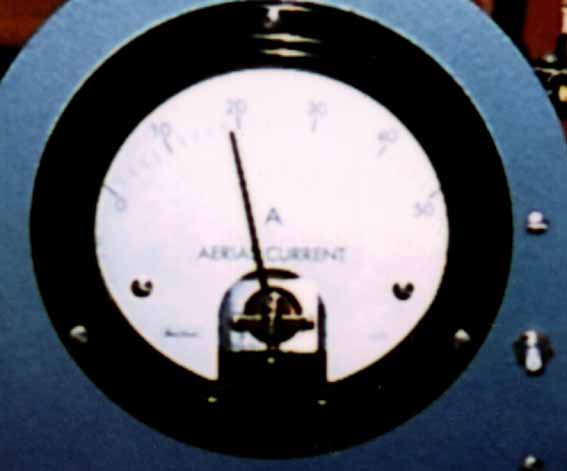
The Decca Stations had radiated powers ranging from about 70 Watts at the Purple Frequency rising to about 120 Watts on the Green.
The 19A antenna current (difficult to see on the scanned image but quite readable on the original 35mm slide) would probably indicate that this was taken at the Purple Station. I vaguely remember that the Green antenna current was in the order of about 12 to 14A.
Multipulse Currents at all stations were in the region of 35 to 40A.

A view of the coils, the tuning capacitors - the term condenser was still used by Decca - and the mast lighting transformer. The tube running along the floor at the base of the trestle is for the capacitor breathers which were connected to a silica jell desiccator.

A view of the lead out to the Mast. The cables for the mast lighting supply passed down the centre of the copper tube - actually standard UK domestic water tube such as used in any central heating system complete with "Yorkshire" solder ring couplings.
A close up of the Mast Lighting transformer. This was basically two toroids inter-coupled together. The "hot" toroid sat on insulators comprising of two "Pyrex" glass tubes. Each mast had three sets of red aviation warning lights - two half way up the mast at the 50 metre level, and the third at the top. These were standard incandescent bulbs.
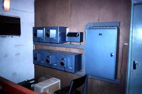
A view of the ATAM - Aerial Tuning And Matching Unit - the large blue box on the wall and the 5 Line Matching Transformers to the left - one for each transmitter. I can't recall the function of the small blue unit with the black panel.
Each Line Matching Transformer was actually a "T" matching network using a variometer as the variable element. On the front of each transformer was a servo motor which would be controlled directly by the adjacent ATAM unit.
The ATAM unit had two functions, to adjust each of the Line Matching Transformers for a minimum VSWR on the feeders between the transmitters in the main building and the coil house, and to keep the antenna system on tune for which the Station's primary Lane (carrier) frequency was used.
Antenna tuning of the other frequencies as used for the Multi-pulse were achieved by only the mechanical tracking provided as the variometer in the centre coil and the moving section of the trestle were adjusted.
A view of the tuning capacitors. The plastic tubes going to the capacitor cases were breathers.
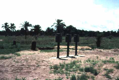
These were called APS (Anti-precipitation Static) Antennas and were used at the slave station to receive the Master signal so that the slave could lock to it.
The APSs were in fact active antennas mounted in homebrew plastic beer barrels which had been coated with a graphite solution. The graphite coating was to provide a large surface area and hence capacitance in order to reduce the level of the static voltage from the charge on the rain particles. The APS barrel was grounded via a high value resistor to "leak" any charge to ground but without affecting the overall performance of the antenna for receiving the Master signal.
Inside the barrel was an active antenna. The antenna element was a section of copper foil, about 300mm wide wrapped around a section of plastic pipe. This was connected to a broadband pre-amplifier with a J-FET input and a bipolar transistor as an output buffer. One APS was connected to each of the phase control bays in the building. Power for the pre-amplifier was fed down the coax.
Obviously, there were no APS antennas at the Master Station.
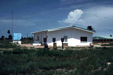
A view of the APS antennas at the Green Station, Badagary.
The blue tank to the left of the building was the bulk fuel supply for the diesel generators. The short mast (left of the tank) is for a SMC trapped dipole for the HF SSB radio used for inter-site communications.
Last update4/5/2001